2 node address setting, Node address setting, Node address setting ( 36) – Lenze E94AYCEP User Manual
Page 35: 6commissioning
Lenze · E94AYCEP communication module (POWERLINK MN/CN) · Communication Manual · DMS 6.0 EN · 02/2014 · TD17
36
6
Commissioning
6.2
Node address setting
_ _ _ _ _ _ _ _ _ _ _ _ _ _ _ _ _ _ _ _ _ _ _ _ _ _ _ _ _ _ _ _ _ _ _ _ _ _ _ _ _ _ _ _ _ _ _ _ _ _ _ _ _ _ _ _ _ _ _ _ _ _ _ _
6.2
Node address setting
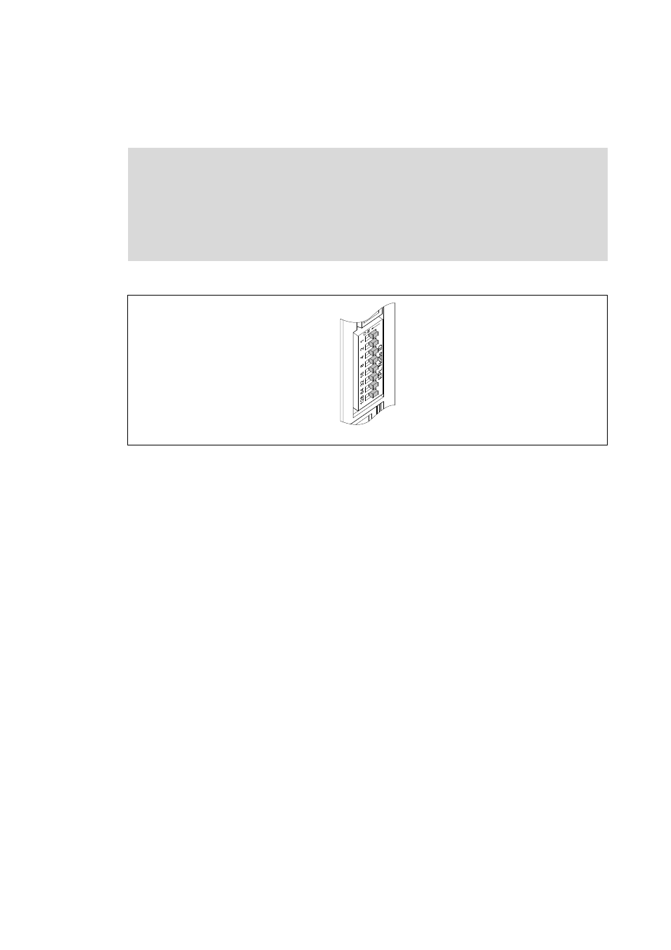
The POWERLINK node address (node ID) is set via the front DIP switches.
[6-1]
DIP switch
• The labelling on the housing corresponds to the valencies of the individual DIP switches for
determining the node address (Node ID).
• Lenze setting for DIP switches 1 ... 128 = OFF (invalid value "0")
• Valid addresses in the POWERLINK network for the communication module:
• 240: Managing Node
The Managing Node mode" supports max. 50 nodes.
• 1 … 100: Controlled Node with Lenze module E94AYCEP as Managing Node
• 1 … 239: Controlled Node with Managing Node of another manufacturer
• The corresponding Ethernet IP address of the communication module results from the address
setting of the DIP switches:
IP address: 192.168.100.[Node ID]
Note!
• Each network node address must only be used once.
• The node address setting in the configuration software (e.g. »Engineer«) and the DIP
switches must be identical for each node.
• Switch the voltage supply of the communication module off and on again to activate
changed settings.
E94YCEP001D