Figure 3-22: angle adjustment plate installation – Landoll 2430 Weatherproofer I User Manual
Page 51
ASSEMBLY INSTRUCTIONS
3-31
Finishing Combo w/ Conditioner
Reel Installation (Option)
NOTES
Refer to Figure 3-17 for hydraulic diagram.
See Figure 2-7 for finishing combo w/ conditioner reel
placement dimensions.
1.
Attach combo attachment harrow arms to rear of
main frame and wings using 1-8 x 7-1/2 hex head
cap screws and hex lock nuts (See Figure 3-21.)
2.
Install the manifolds to the manifold brackets on the
main and wing frames using 1/2-13 x 3-1/2 hex head
cap screws and hex lock nuts.
3.
Install fittings into manifold according to Figure 3-17.
4.
Install hoses per Figure 3-17.
5.
Install steel plugs in any remaining open manifold or
valve ports.
6.
Pull out 1-8 x 7 hex head cap screw and attach
wrench combo plate to frame using the existing
hardware (See Figure 3-19.)
7.
Install wrench harrow adjustment plate to wrench
combo plate using quick hitch pin.
8.
Attach harrow adjustment combo attachment tube to
3 row coil tine harrow assembly using spring clamp
u-bolts, harrow stiffener plates, and 5/8-11 flange
head serrated nuts.
9.
Attach combo attachment harrow arms to the
conditioner reel/gang bar assembly using gang bar
mount plate, 3/4-16 X 6 hex head cap screws and
double hex lock nuts.
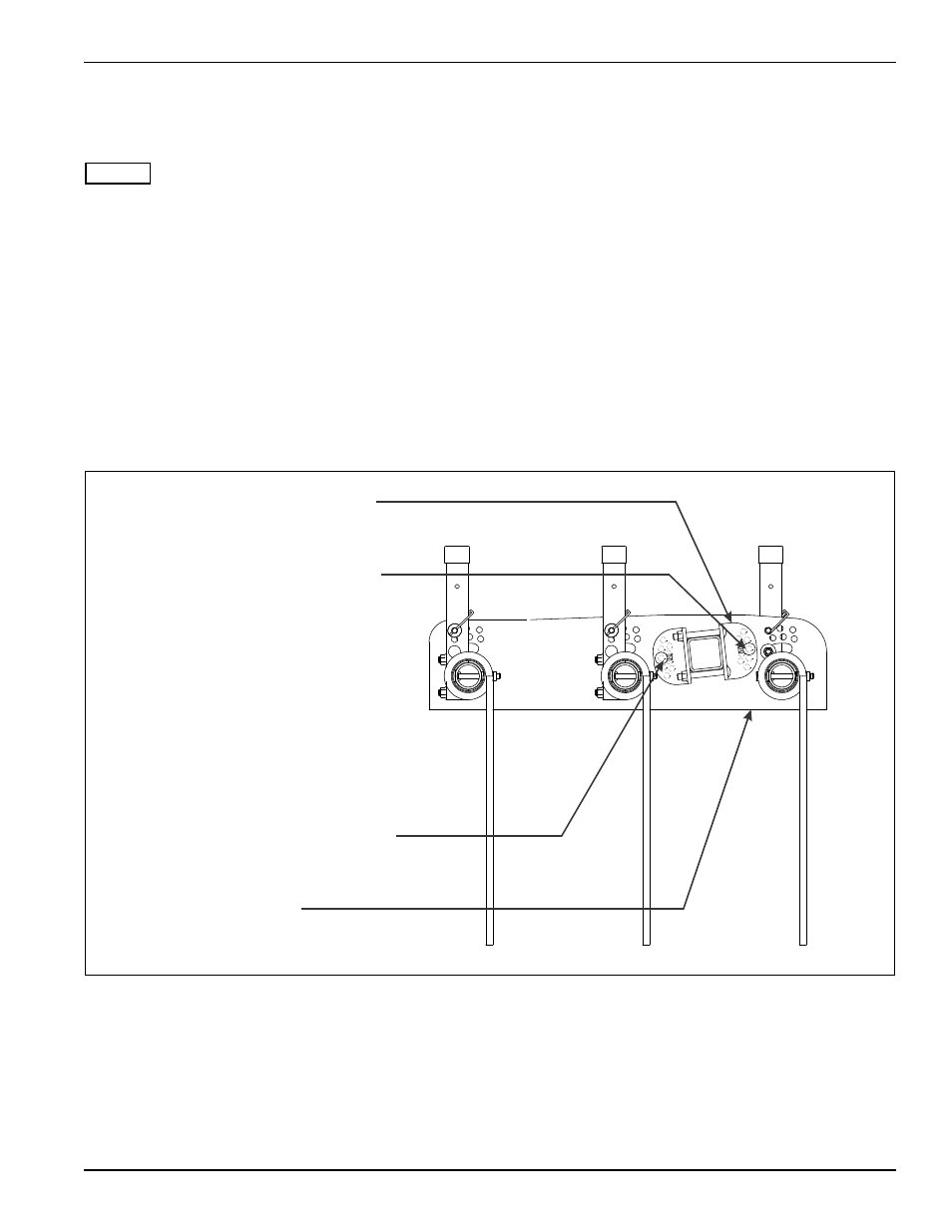
10. Install 1/2-13 x 1-1/4 round head square neck screws
through angle adjustment plate and gang bar plate
as shown in Figure 3-22.
Figure 3-22: Angle Adjustment Plate Installation
ANGLE ADJUSTMENT PLATE
1/2-13 X 1-1/4 RD HEAD SQ
NECK SCREW (PLACE IN
2ND INNER HOLE FROM TOP)
1/2-13 X 1-1/4 RD HEAD SQ
NECK SCREW (PLACE IN 2ND
INNER HOLE FROM BOTTOM)
GANG BAR PLATE
2430 combo angle adjustment plate