Hydraulic installation – Landoll 2430 Weatherproofer I User Manual
Page 40
3-20
F-652-0912 Edition
ASSEMBLY INSTRUCTIONS
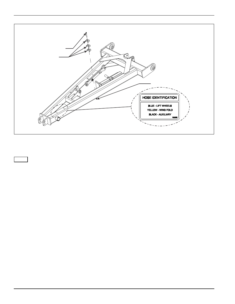
Figure 3-11: Hitch Hose Clamps and Color Designation
Hydraulic Installation
NOTE
Refer to Figures 3-9 through 3-11 for hydraulic
diagrams for each model.
1.
Install straight adapters and 90º adapter into relief
valve as shown in Figures 3-9 through 3-11.
2.
Assemble relief valve assembly into port A in the
front of the manifold.
3.
Install the manifold to the manifold bracket on the
frame using 1/2-13 x 3-1/2 hex head cap screws and
hex lock nuts.
4.
Install fittings into manifold according to Figures 3-9
through 3-11.
5.
Install wing fold system hoses per Figure 3-10.
6.
Hold each system of hoses in place using 3/8-16 x 3
hex head cap screw, hose clamps, and hex lock nut
(See Figure 3-11.)
7.
Install steel plugs in any remaining open manifold or
valve ports.
8.
Install hose wraps around system hoses per hose
identification decal near hose couplers, putting both
hoses inside wrap(See Figure 3-11.)
3/8-16 X 3 OR
3/8-16 X 4 HEX
HEAD CAP SCREW
HOSE CLAMPS
3/8-16 HEX LOCK NUT
2430 hitch hose clamps
- 4630-36 Folding Seeder Operators Manual v.F-640-0513 05/2013 (36 pages)
- 4630-36 Folding Seeder Operators Manual v.F-640-0513 05/2013 (40 pages)
- 4630-36 Folding Seeder Parts Manual v.F-641-1213 12/2013 (76 pages)
- 4630-36 Folding Seeder Operators Manual v.F-640-0313 03/2013 (40 pages)
- 4630-36 Folding Seeder Parts Manual v.F-641-0313 03/2013 (70 pages)
- 4630-36 Folding Seeder Parts Manual v.F-641-0513 05/2013 (70 pages)
- 3K063_XL Wing to Center Frame Installation (1 page)
- 3K033_2K314 ASSEMBLY ADDENDUM (1 page)
- 3J061 BRUSH AGITATOR KIT FOR BRILLION SEEDERS Installation (2 pages)
- 2P112 MID-MOUNT HITCH KIT LAND COMMANDER III (4 pages)
- 2K778 BRACKET COIL TINE DRAG ASSEMBLY ON BRILLION MODEL CMD CULTIVATORS (1 page)
- SL ADDITIONAL SEEBOX DIVIDERS (1 page)
- PIVOT PLATE MID-SIZE LAND COMMANDER III (1 page)
- 1P153 - Electric Clutch Kit for Seeders (1 page)
- 1P120 PULL-TYPE LIFT ASSIST KIT (2 pages)
- 9K871 LIFT ASSIST KIT WITH 38 SHANK SPACING (2 pages)
- 164703 PT PULVERIZER WARNING LIGHT (12 pages)
- LCS9151 LANDCOMMANDER (7 pages)
- M-88 TRANSPORT LINK (2 pages)
- 3K997 AUXILIARY CYLINDER KNIT (2 pages)
- 3K915 (Soil Commander I) (1 page)
- 3K914 REAR HITCH KIT (1 page)
- 3K695 V-Leveler (3 pages)
- REAR CUSHION KIT for LANDCOMMANDER (5 pages)
- 5D045 CENTER CUT KIT (1 page)
- 4K647 FLAIR SHREDDER V-BELT (1 page)
- 5K977 TIRE TRACK REMOVER KIT (2 pages)
- 5K282 WARNING LIGHT KIT (2 pages)
- 5K145 WARNING LIGHT KIT (2 pages)
- W-360 Rear S-Tine Spacer (2 pages)
- 175116 Trunnion Bearing Retrofit Kit (14 pages)
- 174282 FRAME REPLACEMENT KIT (4 pages)
- 173531 FRAME STABILIZER KIT (10 pages)
- 171824 SHIM KIT (4 pages)
- 9K446 Hydraulic Conversion Kit (2 pages)
- ML SERIES TOOTH CONTROL KITS (22 pages)
- SMT-8 Seedbed Mulch Tucker (20 pages)
- 1446/1446-1 FS, FSC, FSB Series Flail Shredder (24 pages)
- BDH512 Double Seeder Hitch (38 pages)
- LSP5 Landscape Grass Seeder (34 pages)
- SL/SLB/SLP/SLPB/SLPB TURFMAKER III (58 pages)
- SL 8, 10, 12 Turfmaker Seeder (56 pages)
- M-1241 TRANSPORT PULVI-MULCHER (30 pages)
- ML/MLS/MLC 1483, 1643, 1803 RIGID PULVI-MULCHER (52 pages)
- ML2253 18,9 RIGID PULVI-MULCHER (46 pages)