Light installation (prior to august, 2013) – Landoll 2430 Weatherproofer I User Manual
Page 42
3-22
F-652-0912 Edition
ASSEMBLY INSTRUCTIONS
Figure 3-13: Light and SMV Bracket Installation (Prior to August, 2013)
Light Installation (Prior to
August, 2013)
NOTE
See Figures 2-1 thru 2-4 for light bracket placement. If
no dimension is given for a bracket, it should be located
against frame member as shown in drawing.
1.
Attach inner tail light mounting bracket supports to
the center frames using 1/2-13 x 8-1/2 hex head cap
screws, warning light bars, and hex lock nuts (See
Figure 3-12.)
2.
Attach outer LH and RH light brackets to frame
weldment using 1/2-13 x 9-1/2 hex head cap screws,
warning light bars, and hex lock nuts.
3.
Attach red brake lamps to inner tail light mounting
bracket supports and amber lamps to outer light
brackets using 1/4-20 x 1-1/4 hex head cap screws
and hex lock nuts.
4.
Connect warning light harnesses to lights. Note that
2-34" harness extensions are required at the rear of
the main harness for adequate length.
5.
Attach SMV emblem and mounting bracket to rear
center frame bar using 1/2-13 x 5-1/2 hex head cap
screws, 1/4-20 x 3/4 hex head cap screws, and hex
lock nuts. The SMV sign should be centered on the
rear bar of the frame.
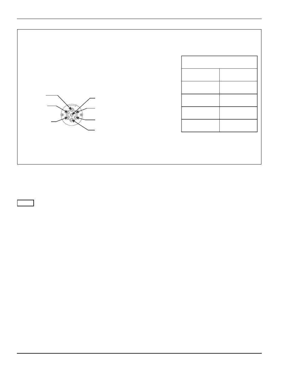
NOTE: IF REPAIRING OR REPLACING THE 7 PIN
CONNECTOR, MATCH THE LETTERS AT THE
BACK OF THE HARNESS TO THE 7 PIN CONNECTOR
AS SHOWN. THE COLOR OF THE WIRE JACKET
DOES NOT NECESSARILY MATCH THE COLOR
MARKING OF THE 7 PIN CONNECTOR.
4-PIN
CONNECTION
7-PIN
CONNECTION
C
A
B
D
BRN. 6
GRN. 5
YEL. 3
GRND. 1
WIRING CHART
#1 WHITE
#2 BLACK
#3 YELLOW
#6 BROWN
#5 GREEN
#4 RED
#7 BLUE
FACING 7-PIN CONNECTOR
electrical connector op