1 single sensor configuration overview and parts, Section 1.4.1 – INFICON Front Load Single Sensor User Manual
Page 14
1 - 4
PN
07
4-
15
6N
Front Load Single and Dual Sensors Operating Manual
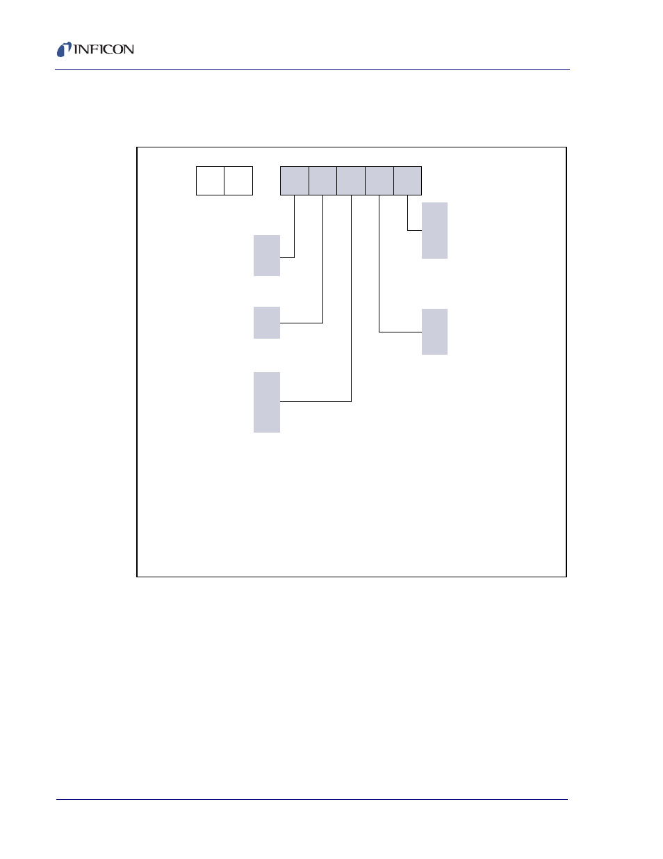
1.4.1 Single Sensor Configuration Overview and Parts
Front Load Single Sensor . . . . . . . . . . . SL-XXXXX, see
.
Figure 1-2 Front Load Single Sensor configurations
Thin Film Manuals CD . . . . . . . . . . . . . . . . . . . . . . . PN 074-5000-G1
Crystal Snatcher. . . . . . . . . . . . . . . . . . . . . . . . . . . . PN 008-007
78.1 cm (30.75 in.) In-Vacuum Cable. . . . . . . . . . . . PN 007-044
(standard length)
152.4 cm (60 in.) In-Vacuum Cable . . . . . . . . . . . . . PN 321-039-G13
(extended length)
Molybdenum Disulfide in Alcohol . . . . . . . . . . . . . . . PN 750-191-G1
(provided only with shuttered sensors)
Tube Bender Kit . . . . . . . . . . . . . . . . . . . . . . . . . . . . PN 750-037-G1
(provided only with non-welded sensors)
S L –
A
B
0
3
4
0
1
0
7
8
E
G
NOTE 1:
Orders for a WELDED sensor/feedthrough combination cannot
be accepted without a completed sensor length specification
form (provided by INFICON). Once a welded sensor order is
confirmed, it can not be canceled.
NOTE 2:
Feedthrough configuration varies depending on options
selected (with or without shutter, type of feedthrough, etc).
Example: SL-A0E37 uses feedthrough PN 002-042 while
SL-A1E37 uses feedthrough PN 750-030-G1.
Type of Sensor
(Includes in-vacuum cable.
Crystals sold separately.)
Standard sensor
(water lines parallel)
Right angle sensor
(water lines perpendicular)
Shutter Assembly – SEE NOTE 4
None
Standard shutter
Length of Sensor –
SEE NOTES 1 and 3
Standard length:
20.3 to 71.1 cm (8 to 28 in.)
includes 78.1 cm (30.75 in.)
in-vacuum cable. SEE NOTE 6
Extended length:
71.1 to 121.9 cm (28 to 48 in.)
includes 152.4 cm (60 in.)
in-vacuum cable. SEE NOTE 6
Feedthrough Connection –
SEE NOTE 4
Sensor not connection to
feedthrough
Sensor welded to feedthrough
Feedthrough equipped with
Ultra-Torr
®
compression fittings
(allows for adjustable sensor
length)
Feedthrough – SEE NOTE 2
None
1 in. bolt
CF40
NOTE 3:
Sensor lengths are measured from center of the crystal to the
vacuum side (sealing surface) of the feedthrough (see length
specification form).
NOTE 4:
Sensors ordered with shutters and 1 in. bolt style feedthrough can
only be welded (compression fittings not available).
NOTE 5:
Front Load sensors ordered with a CF40 feedthrough and a shutter
can not be welded due to dimensional limits of the CF40.
NOTE 6:
For sensors ordered without a weld connection (option “0” or “8”),
tubes are made to a length of approximately 76.2 cm (30 in.) for
“E” length and approximately 121.9 cm (48 in.) for “G” length
sensors.
Operation with a 152.4 cm (60 in.) cable requires a monitor /
controller with ModeLock technology (XTC/3, IC6, Cygnus 2).