1 measurement system check, Figure 5-8 – INFICON Front Load Single Sensor User Manual
Page 87
5 - 11
PN
07
4-
15
6N
Front Load Single and Dual Sensors Operating Manual
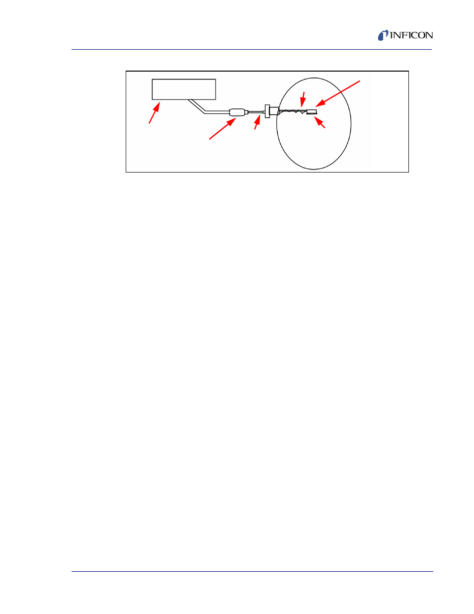
Figure 5-8 Crystal Sensor Emulator attachment points
5.1.3.1 Measurement System Check
1
. Remove the 15.2 cm (6 in.) BNC cable from the
feedthrough at point A.
2
Connect the Crystal Sensor Emulator to the 15.2 cm (6 in.) BNC cable
at point A.
If the Crystal Fail message disappears after approximately five seconds,
the sensor or feedthrough is the cause of the Crystal Fail. Reinstall the 15.2
cm (6 in.) BNC cable to the feedthrough and proceed to
.
If the Crystal Fail message remains, the controller / monitor, or XIU /
oscillator, or their associated cables are the cause of the Crystal Fail. Refer
to the controller or monitor operating manual for troubleshooting
information.
Thin Film
Controller
Crystal Interface
Unit (Oscillator)
Sensor Head
A
In-Vacuum
C
cable
B
Crystal
Holder
BNC
Cable