Chapter 3 sqs-242 software – INFICON SID-242 Thin Film Deposition Controller User Manual
Page 53
Chapter 3 SQS-242 Software
3-23
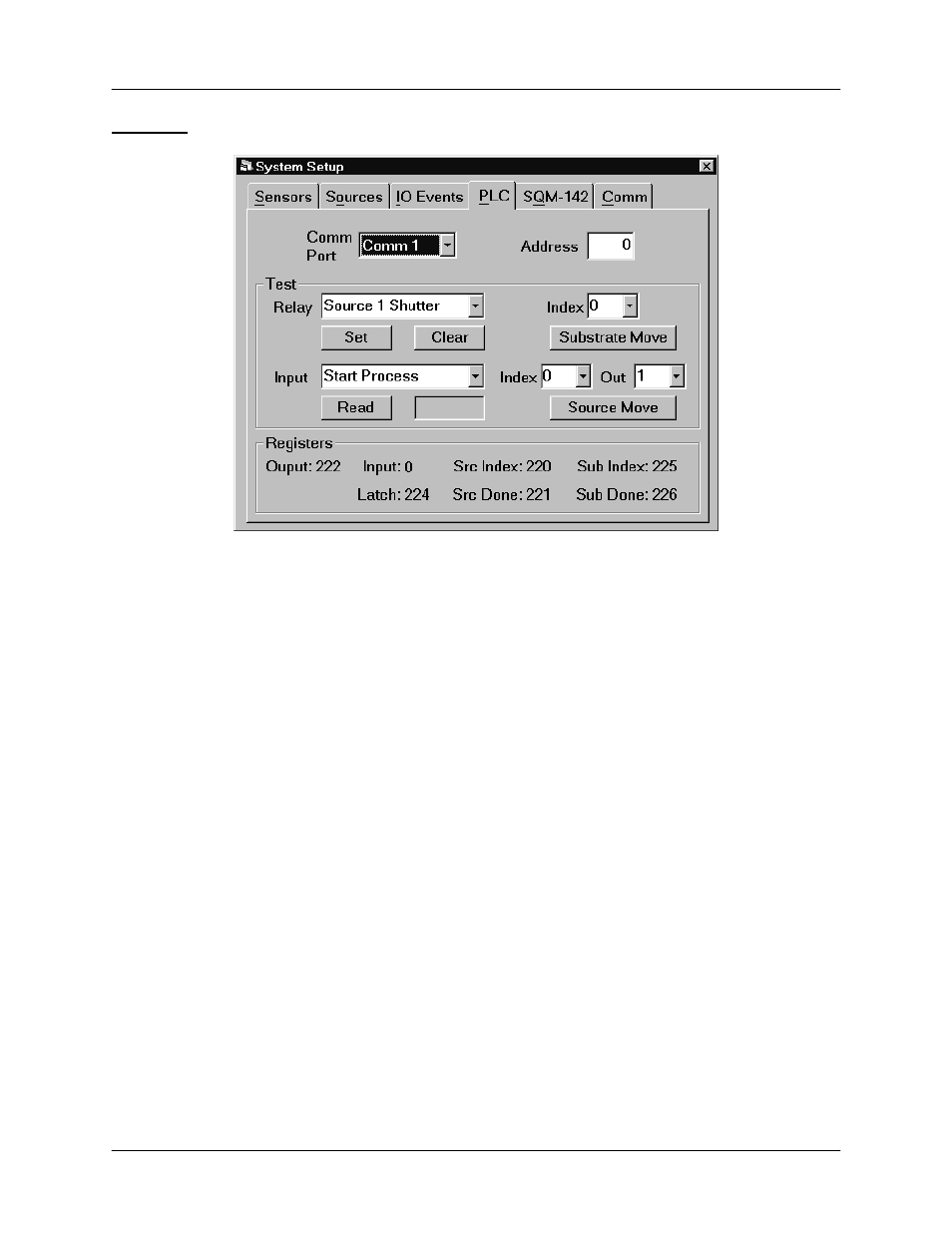
PLC Tab
Comm Port: Selects the serial port used to communicate with the PLC. The Comm
Port drop down lists the available ports. However, some of the ports may be used by
other devices (modem, mouse, etc.). Select Disabled to prevent I/O from using the
PLC.
Address: Several PLCs can be controlled from a single computer Comm Port by
connecting their expansion ports. The slave address of each such PLC is usually set by
a rotary or dip switch, and must be unique. Single PLC systems usually use Address 0.
Consult your PLC User Manual.
Test: The Test section provides a simple means of testing your PLC communications
and digital I/O wiring. To set a relay on the PLC, go to the Digital I/O tab and find which
I/O event is assigned to that relay. On the PLC tab, select the same event in the Test
Relay dropdown, then click Set. The assigned Relay# should close. Click Clear to
open the relay. Use the Source and Substrate Move sections to test indexers.
To test a digital input, find the Input# that is assigned to an event on the PLC tab.
Select the input event in the dropdown, then click Read Input to verify the state of the
PLC input.
Registers: The PLC used for I/O runs a small monitor program that transfers relay and
input states from the PLC connecting block to internal registers. The SQS-242 software
reads/writes to those registers though the PLC’s Comm port. The registers shown are
those that have been programmed for your PLC. Because their redefinition is not a
trivial task, these values cannot be changed in the SQS-242 program. Contact Sigma
Instruments if you need to change the internal PLC register definitions.