Connect the wiring, Echo, Lockout station – ETC Echo Lockout Station User Manual
Page 3: N o t e
E T C I n s t a l l a t i o n G u i d e
Echo
™
Lockout Station
Page 3 of 6
Echo
™
Lockout Station
Rotary Switch Assignments
Each station must be set to a unique station address for the assigned space.
By default, these switches are set to Space 1, Station Address 1. Commands
are shared by all devices within a space.
Step 1: Set the Space rotary switch to the desired number (1 thru 16) for the
space you want the station to provide lockout.
Step 2: Set the Address rotary switch to the desired address (1 thru 16) for the
station identification in the selected Space.
Connect the Wiring
Step 1: Pull all required wiring (data+, data-) into the back box. As needed, pull
an additional ESD ground wire (required only when the station is not
installed in grounded metal conduit).
Step 2: Connect station ESD ground wire pigtail.
a: Strip 3/8” (9-10mm) of insulation from the ends of the station ground wire
pigtail, provided in the termination kit, and the incoming ground wire to
the grounded metal back box.
b: Use one WAGO connector, provided in the termination kit, to connect
the station ESD ground pigtail and the incoming ground. For systems
using grounded metal conduit, connect the ground pigtail to the metal
back box ground location.
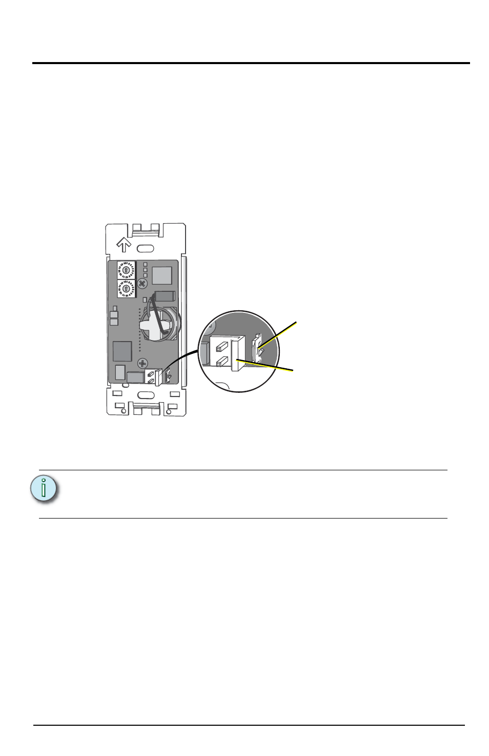
c: Install the ESD ground wire pigtail Faston connector to the spade
terminal on the station electronics.
N o t e :
A ground connection (14 AWG) is required between every
station and back box, even when installed with grounded
metal conduit.
Ground spade
Data connector