Field applications – ERICO EST401 ERITECH Clamp-on Ground Resistance Tester User Manual
Page 21
19
www.erico.com
Field Applications
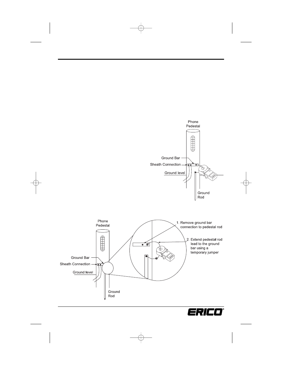
Phone Pedestal
Provide sufficient room for the EST401 jaws, which must be able to close easily around
the conductor (Fig. 21). The jaws can be placed around the ground rod itself.
Note: If not enough room is available for this task refer to Fig. 22 and continue with
this example. The clamp must be placed so that the jaws are in an electrical path from
the sheath bond(s) or ground bar to the ground rod(s) as the circuit provides.
Select the current range “A.” Clamp onto the ground conductor and measure the ground
current. The maximum current range is 30A. If the ground current exceeds 5A, ground
resistance measurements are not possible. Do not proceed further with the measurement.
Remove the clamp-on tester from the circuit, noting the location for maintenance, and
continue to the next test location.
After noting the ground current, select the ground
resistance range “Ω” and measure the resistance
directly. The reading you measure with the EST401
indicates the resistance of not just the rod, but
also the connection to the sheath ground and all
bonding connections between the sheath bond
and the rod.
A high reading indicates one or more of the
following:
A. Poor ground rod
B. Open ground conductor
C. High resistance bonds on the rod or splices
on the conductor. Also look for bad connections
on the ground bar to the sheath(s).
Note: This same test can be done using the TIP instead
of the sheath ground. However keep in mind that this
is intended to be grounded only back at the central office.
Figure 21
Figure 22
E1154IS06 EST401_5.qxd:E1154IS06 9/25/06 1:46 PM Page 19