Principle of operation – ERICO EST401 ERITECH Clamp-on Ground Resistance Tester User Manual
Page 15
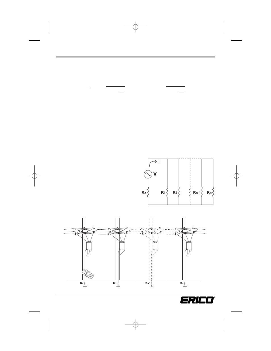
A typically grounded distribution system may be simulated by the basic circuit shown in
Fig. 12 or an equivalent circuit, shown in Fig. 13. If voltage (V) is applied to any measured
grounding electrode Rx through a special transformer, current (I) flows through the circuit,
thereby establishing the following equation:
Therefore, V/ I = Rx is established. If I is detected and measured with V kept constant, the
measured grounding electrode resistance Rx can be obtained. A signal is fed to a special
transformer via a power amplifier from a 2003Hz constant voltage oscillator. The resulting
current is then sensed by a detection CT. An active filter is used to dampen earth current at
commercial frequency and high-frequency noise.
Example: If we clamp around any grounding electrode in a multi-grounded system, the
measured value of the electrode under test will be the resistance of that particular rod in
series with the equivalent parallel resistance value that the rest of the multi-grounded sys-
tem represents. If we had an electrical system that had 101 grounding electrodes and each
had a resistance value of 25Ω, and we were to clamp around any electrode in the system,
the measured value would be 25Ω in series with the equivalent parallel resistance or 0.25Ω.
The displayed value would be 25.2Ω (instrument resolution to 0.1Ω).
V/I = 25Ω + 0.25Ω
Rx = 25.2Ω
In most field applications, the number of
electrodes that make up a multi-grounded
system would be higher, therefore the
equivalent parallel resistance is negligible
with respect to the rod under test.
13
www.erico.com
Principle of Operation
∑
i=1
n
1
Ri
V
I
= Rx +
1
where, usually
Rx »
∑
i=1
n
1
Ri
1
Figure 12
Figure 13
E1154IS06 EST401_5.qxd:E1154IS06 9/25/06 1:46 PM Page 13