Field applications – ERICO EST401 ERITECH Clamp-on Ground Resistance Tester User Manual
Page 16
14
www.erico.com
Field Applications
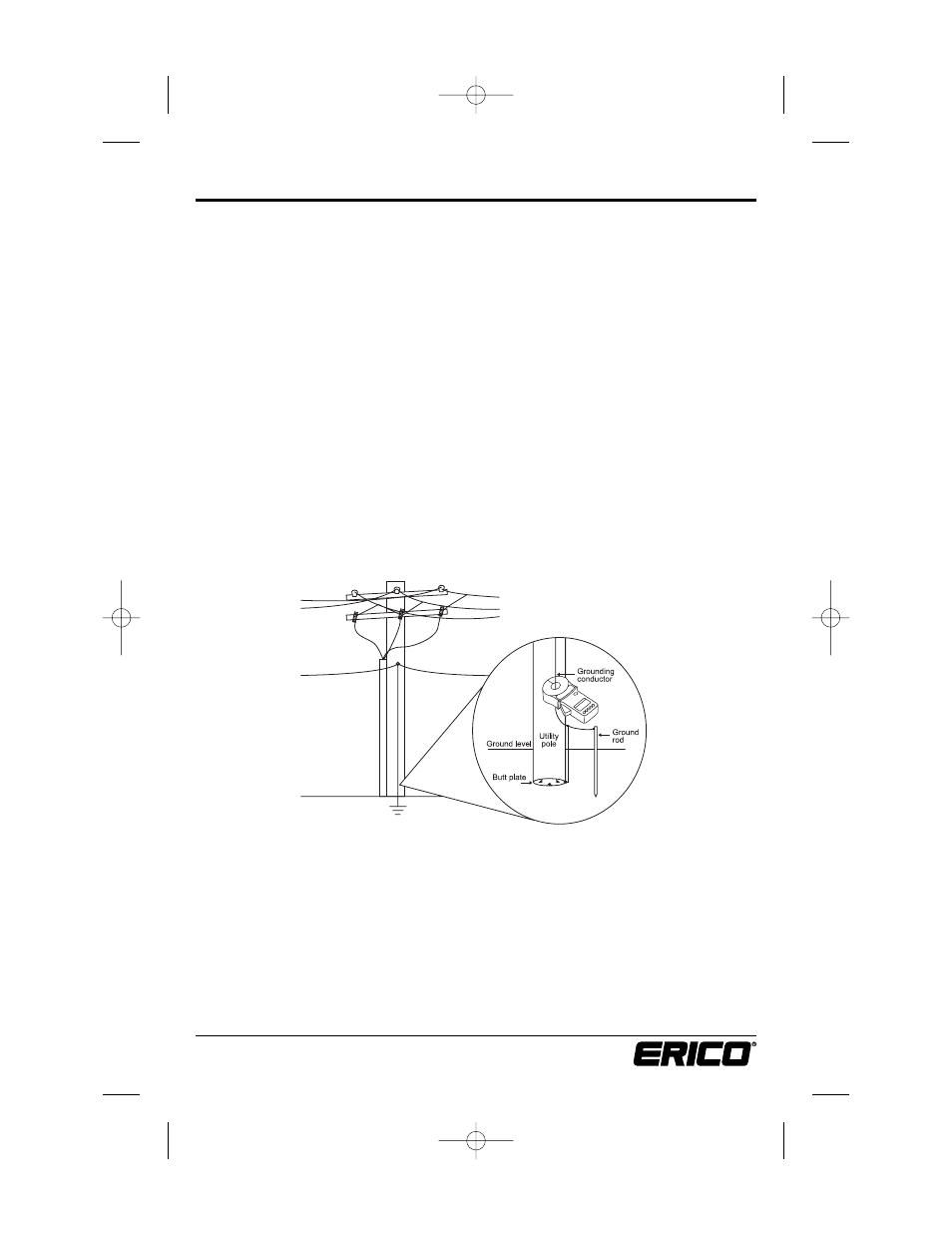
Pole Ground Rods
Remove any molding covering the ground conductor, and provide sufficient room for the
jaws of the clamp-on. The jaws must be able to close easily around the conductor. The jaws
can be placed around the ground rod itself.
Note: The instrument must be placed so that the jaws close around an electrical path from
the system neutral or ground wire to the ground rod or rods as the circuit provides.
Select the current range “A.” Clamp onto the ground conductor and measure the ground
current. The maximum range is 30.00A Trms. However, if the ground current exceeds 5A
or noise exceeds 50V, ground resistance measurements are not possible. Do not proceed
further with the measurement. Remove the instrument from the circuit noting the
location for maintenance and continue to the next test location.
After noting the ground current, select the ground resistance range (Ω) and measure the
resistance directly. The reading you measure with the clamp-on tester indicates not just
the resistance of the rod, but of the connection to the system neutral and all bonding
connections between the neutral and the rod.
Note that in Fig. 14 there is both a butt plate and a ground rod. In this type of circuit, it is
necessary to place the instrument above the bond so that both grounds are included in the
test. For future reference, note the date, Ohms reading, current reading and pole number.
Replace any molding you may have removed from the conductor.
Figure 14
E1154IS06 EST401_5.qxd:E1154IS06 9/25/06 1:46 PM Page 14