Auxiliary feedback port (input mode ya[4]= 2, 0) – ElmoMC SimplIQ Digital Servo Drives-Whistle DC Installation Guide User Manual
Page 62
DC Whistle Installation Guide
Technical Specifications
MAN-DCWHIIG (Ver. 1.101)
62
4.7.9.
Auxiliary Feedback Port (input mode YA[4]= 2, 0)
Feature
Details
Encoder input,
pulse and direction input
A, B, Index
Differential
Output current capability
V
In
Low: 0 V < V
IL
< 0.8 V
V
In
High: 2 V < V
IH
< 5 V
Maximum absolute voltage: 0 < V
In
< 5.5 V
Input current: ±1 µA
Encoder/Hall supply voltage
5 V + 5%
Maximum encoder supply current
200 mA
Available as options
Differential Encoder inputs
Differential Pulse and Direction inputs
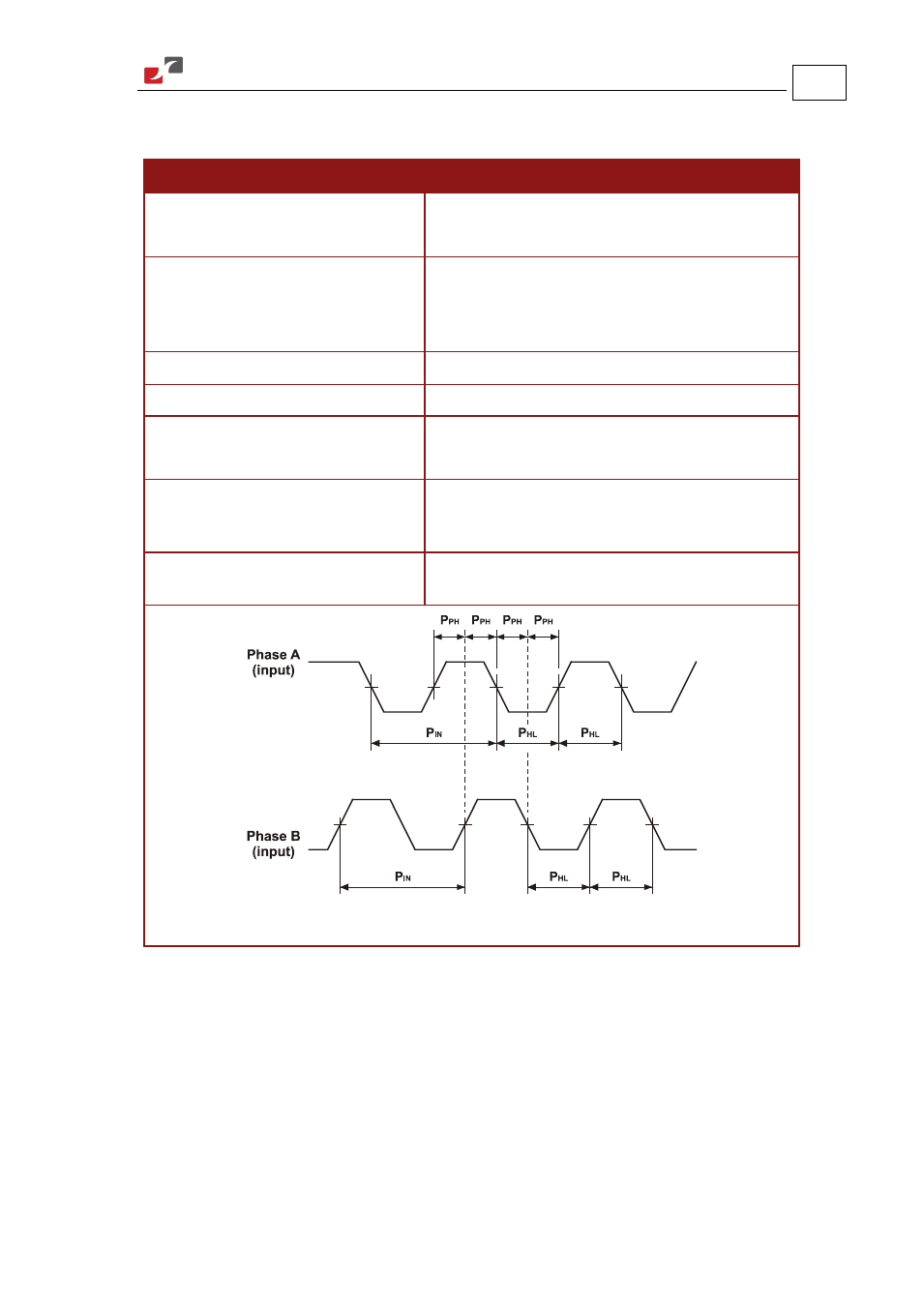
Edge separation between A & B
Programmable number of clocks to allow adequate
noise filtering at remote receiver of emulated
encoder signals
Index (marker)
Length of pulse is one quadrature (one quarter of
an encoder cycle) and synchronized to A&B
Figure 28: Auxiliary Feedback - Encoder Phase Diagram
- Gold Line Digital Servo Drives-Gold Bell (84 pages)
- Gold Line Digital Servo Drives-Gold DC Bell (61 pages)
- Gold Line Digital Servo Drives-Gold Whistle (85 pages)
- Gold Line Digital Servo Drives-Gold Solo Whistle (61 pages)
- Gold Line Digital Servo Drives-Gold Drum Ver 1_400 D-Sub connectors (67 pages)
- Gold Line Digital Servo Drives-Gold Drum Ver 1_400 RJ-45 connectors (67 pages)
- Gold Line Digital Servo Drives-Gold DC Whistle (61 pages)
- Gold Line Digital Servo Drives-Gold Drum HV (102 pages)
- Gold Line Digital Servo Drives-Gold Duo (59 pages)
- Gold Line Digital Servo Drives-Gold Solo Whistle Cable Kit (16 pages)
- Gold Line Digital Servo Drives-Gold Drum Cable Kit RJ-45 connectors (17 pages)
- Gold Line Digital Servo Drives-Gold DC Whistle Cable Kit (13 pages)
- Gold Line Digital Servo Drives-Gold Drum HV Cable Kit (18 pages)
- Gold Line Digital Servo Drives-Gold Duo Cable Kit (12 pages)
- Gold Line Digital Servo Drives-Gold Guitar (84 pages)
- Gold Line Digital Servo Drives-Gold Solo Guitar (65 pages)
- Gold Line Digital Servo Drives-Gold Cello (59 pages)
- Gold Line Digital Servo Drives-Gold Trombone (92 pages)
- Gold Line Digital Servo Drives-Gold Solo Trombone (110 pages)
- Gold Line Digital Servo Drives-Gold DC Trombone (69 pages)
- Gold Line Digital Servo Drives-Gold Tuba (81 pages)
- Gold Line Digital Servo Drives-Gold Bassoon (66 pages)
- Gold Line Digital Servo Drives-Gold Solo Guitar Cable Kit (12 pages)
- Gold Line Digital Servo Drives-Gold Cello Cable Kit (15 pages)
- Gold Line Digital Servo Drives-Gold Solo Trombone Cable Kit (16 pages)
- Gold Line Digital Servo Drives-Gold DC Trombone Cable Kit (15 pages)
- Gold Line Digital Servo Drives-Gold Tuba Cable Kit (20 pages)
- Gold Line Digital Servo Drives-Gold Bassoon Cable Kit (16 pages)
- ExtrIQ Gold Line Servo Drives-Gold Hornet (88 pages)
- ExtrIQ Gold Line Servo Drives-Gold Solo Hornet (90 pages)
- ExtrIQ Gold Line Servo Drives-Gold Eagle (68 pages)
- ExtrIQ Gold Line Servo Drives-Gold Hawk (90 pages)
- ExtrIQ Gold Line Servo Drives-Gold Panther (64 pages)
- ExtrIQ Gold Line Servo Drives-Gold Tiger (64 pages)
- Multi-Axis Motion Controller-Gold Maestro (32 pages)
- SimplIQ Digital Servo Drives-Bell Installation Guide (57 pages)
- SimplIQ Digital Servo Drives-Bell Getting Started (94 pages)
- SimplIQ Digital Servo Drives-Bell Command Reference (315 pages)
- SimplIQ Digital Servo Drives-Bell Evaluation Board User Guide (93 pages)
- SimplIQ Digital Servo Drives-Tweeter Installation Guide (71 pages)
- SimplIQ Digital Servo Drives-Whi-Solo Installation Guide (69 pages)
- SimplIQ Digital Servo Drives-Whi-Solo Cable Kit (10 pages)
- SimplIQ Digital Servo Drives-Whi-Duo Installation Guide (69 pages)
- SimplIQ Digital Servo Drives-Whi-Trio Installation Guide (62 pages)