ElmoMC SimplIQ Digital Servo Drives-Whistle DC Installation Guide User Manual
Page 27
DC Whistle Installation Guide
Installation
MAN-DCWHIIG (Ver. 1.101)
27
Resolver
Tachometer and Potentiometer
DC-WHI-
XX/YYY
R
DC-WHI
XX/YYY
T
Pin
Signal
Function
Signal
Function
1
+5V
Encoder/Hall +5V supply
+5V
Encoder/Hall +5V supply
2
SUPRET
Supply return
SUPRET
Supply return
3
S1
Sine A
Tac 1+
Tacho Input 1 Pos. (20 V max)
4
S3
Sine A complement
Tac 1-
Tacho Input 1 Neg. (20 V max)
5
S2
Cosine B
Tac 2+
Tacho Input 2 Pos. (50 V max)
6
S4
Cosine B complement
Tac 2-
Tacho Input 2 Neg. (50 V max)
7
R1
Vref f=1/TS, 50 mA Max.
POT
Potentiometer Input
8
R2
Vref complement
f= 1/TS, 50 mA Max
NC
-
9
NC
-
HA
Hall sensor A input
10
NC
-
HB
Hall sensor B input
11
NC
-
HC
Hall sensor C input
12
SUPRET
Supply return
SUPRET
Supply return
Table 8: Main Feedback Cable Pin Assignment for Resolver, Tachometer &Potentiometer
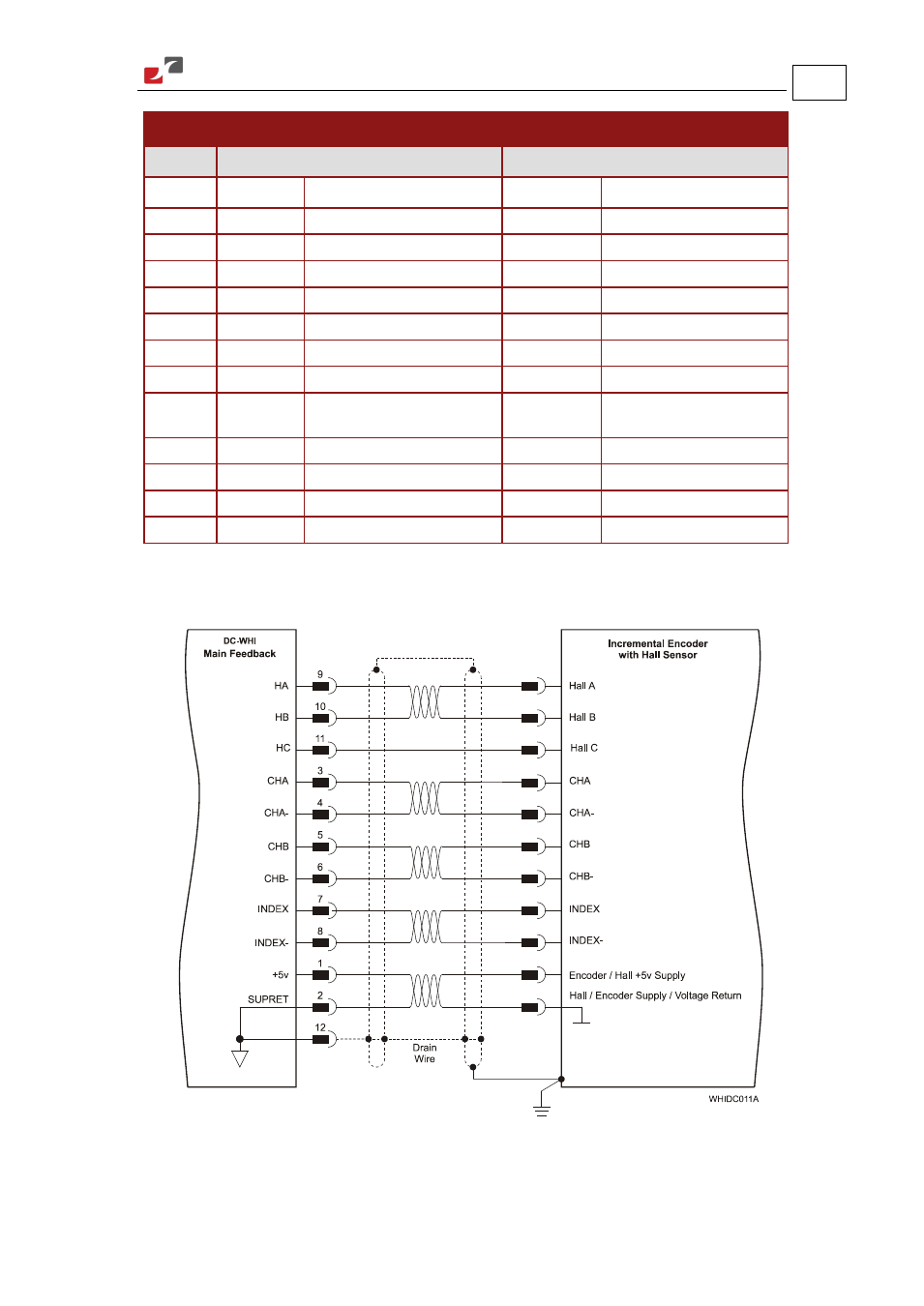
Figure 9: Main Feedback- Incremental Encoder with Digital Halls Sensors Connection Diagram
- Gold Line Digital Servo Drives-Gold Bell (84 pages)
- Gold Line Digital Servo Drives-Gold DC Bell (61 pages)
- Gold Line Digital Servo Drives-Gold Whistle (85 pages)
- Gold Line Digital Servo Drives-Gold Solo Whistle (61 pages)
- Gold Line Digital Servo Drives-Gold Drum Ver 1_400 D-Sub connectors (67 pages)
- Gold Line Digital Servo Drives-Gold Drum Ver 1_400 RJ-45 connectors (67 pages)
- Gold Line Digital Servo Drives-Gold DC Whistle (61 pages)
- Gold Line Digital Servo Drives-Gold Drum HV (102 pages)
- Gold Line Digital Servo Drives-Gold Duo (59 pages)
- Gold Line Digital Servo Drives-Gold Solo Whistle Cable Kit (16 pages)
- Gold Line Digital Servo Drives-Gold Drum Cable Kit RJ-45 connectors (17 pages)
- Gold Line Digital Servo Drives-Gold DC Whistle Cable Kit (13 pages)
- Gold Line Digital Servo Drives-Gold Drum HV Cable Kit (18 pages)
- Gold Line Digital Servo Drives-Gold Duo Cable Kit (12 pages)
- Gold Line Digital Servo Drives-Gold Guitar (84 pages)
- Gold Line Digital Servo Drives-Gold Solo Guitar (65 pages)
- Gold Line Digital Servo Drives-Gold Cello (59 pages)
- Gold Line Digital Servo Drives-Gold Trombone (92 pages)
- Gold Line Digital Servo Drives-Gold Solo Trombone (110 pages)
- Gold Line Digital Servo Drives-Gold DC Trombone (69 pages)
- Gold Line Digital Servo Drives-Gold Tuba (81 pages)
- Gold Line Digital Servo Drives-Gold Bassoon (66 pages)
- Gold Line Digital Servo Drives-Gold Solo Guitar Cable Kit (12 pages)
- Gold Line Digital Servo Drives-Gold Cello Cable Kit (15 pages)
- Gold Line Digital Servo Drives-Gold Solo Trombone Cable Kit (16 pages)
- Gold Line Digital Servo Drives-Gold DC Trombone Cable Kit (15 pages)
- Gold Line Digital Servo Drives-Gold Tuba Cable Kit (20 pages)
- Gold Line Digital Servo Drives-Gold Bassoon Cable Kit (16 pages)
- ExtrIQ Gold Line Servo Drives-Gold Hornet (88 pages)
- ExtrIQ Gold Line Servo Drives-Gold Solo Hornet (90 pages)
- ExtrIQ Gold Line Servo Drives-Gold Eagle (68 pages)
- ExtrIQ Gold Line Servo Drives-Gold Hawk (90 pages)
- ExtrIQ Gold Line Servo Drives-Gold Panther (64 pages)
- ExtrIQ Gold Line Servo Drives-Gold Tiger (64 pages)
- Multi-Axis Motion Controller-Gold Maestro (32 pages)
- SimplIQ Digital Servo Drives-Bell Installation Guide (57 pages)
- SimplIQ Digital Servo Drives-Bell Getting Started (94 pages)
- SimplIQ Digital Servo Drives-Bell Command Reference (315 pages)
- SimplIQ Digital Servo Drives-Bell Evaluation Board User Guide (93 pages)
- SimplIQ Digital Servo Drives-Tweeter Installation Guide (71 pages)
- SimplIQ Digital Servo Drives-Whi-Solo Installation Guide (69 pages)
- SimplIQ Digital Servo Drives-Whi-Solo Cable Kit (10 pages)
- SimplIQ Digital Servo Drives-Whi-Duo Installation Guide (69 pages)
- SimplIQ Digital Servo Drives-Whi-Trio Installation Guide (62 pages)