System architecture, Power stage, Main feedback input – ElmoMC SimplIQ Digital Servo Drives-Whistle DC Installation Guide User Manual
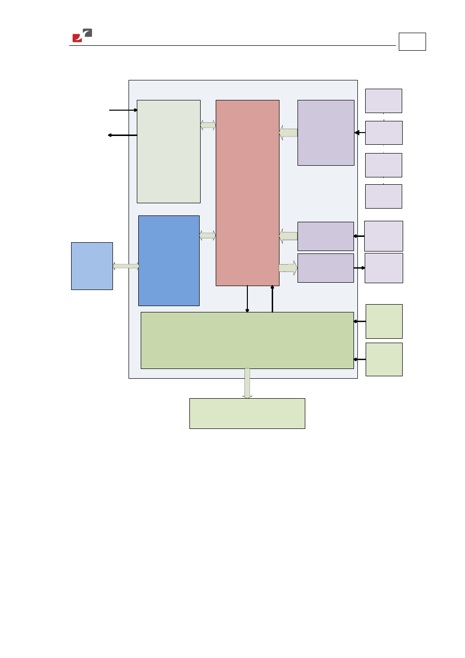
Page 13: Motion control logic, Figure 1: dc whistle system block diagram
DC Whistle Installation Guide
Introduction
MAN-DCWHIIG (Ver. 1.101)
13
2.3. System Architecture
Power Stage
Main
Feedback
Input
Aux. Feedback
Differential Input
Communication
User I/O Interface
Motion
Control
Logic
Incremental
Encoder
Incremental
Encoder
Digital
Inputs
Digital
Outputs
RS232
CANopen
Main DC Power
Supply
Optional DC
Auxiliary Supply
Motor
PWM
Current
Feedback,
Protection
Aux. Feedback
Differential
Output
Other Axis or
Devices
Interpolated
Analog
Encoder
Resolver
Tachometer &
Potentiometer
OR
OR
OR
Figure 1: DC Whistle System Block Diagram
See also other documents in the category ElmoMC Hardware:
- Gold Line Digital Servo Drives-Gold Bell (84 pages)
- Gold Line Digital Servo Drives-Gold DC Bell (61 pages)
- Gold Line Digital Servo Drives-Gold Whistle (85 pages)
- Gold Line Digital Servo Drives-Gold Solo Whistle (61 pages)
- Gold Line Digital Servo Drives-Gold Drum Ver 1_400 D-Sub connectors (67 pages)
- Gold Line Digital Servo Drives-Gold Drum Ver 1_400 RJ-45 connectors (67 pages)
- Gold Line Digital Servo Drives-Gold DC Whistle (61 pages)
- Gold Line Digital Servo Drives-Gold Drum HV (102 pages)
- Gold Line Digital Servo Drives-Gold Duo (59 pages)
- Gold Line Digital Servo Drives-Gold Solo Whistle Cable Kit (16 pages)
- Gold Line Digital Servo Drives-Gold Drum Cable Kit RJ-45 connectors (17 pages)
- Gold Line Digital Servo Drives-Gold DC Whistle Cable Kit (13 pages)
- Gold Line Digital Servo Drives-Gold Drum HV Cable Kit (18 pages)
- Gold Line Digital Servo Drives-Gold Duo Cable Kit (12 pages)
- Gold Line Digital Servo Drives-Gold Guitar (84 pages)
- Gold Line Digital Servo Drives-Gold Solo Guitar (65 pages)
- Gold Line Digital Servo Drives-Gold Cello (59 pages)
- Gold Line Digital Servo Drives-Gold Trombone (92 pages)
- Gold Line Digital Servo Drives-Gold Solo Trombone (110 pages)
- Gold Line Digital Servo Drives-Gold DC Trombone (69 pages)
- Gold Line Digital Servo Drives-Gold Tuba (81 pages)
- Gold Line Digital Servo Drives-Gold Bassoon (66 pages)
- Gold Line Digital Servo Drives-Gold Solo Guitar Cable Kit (12 pages)
- Gold Line Digital Servo Drives-Gold Cello Cable Kit (15 pages)
- Gold Line Digital Servo Drives-Gold Solo Trombone Cable Kit (16 pages)
- Gold Line Digital Servo Drives-Gold DC Trombone Cable Kit (15 pages)
- Gold Line Digital Servo Drives-Gold Tuba Cable Kit (20 pages)
- Gold Line Digital Servo Drives-Gold Bassoon Cable Kit (16 pages)
- ExtrIQ Gold Line Servo Drives-Gold Hornet (88 pages)
- ExtrIQ Gold Line Servo Drives-Gold Solo Hornet (90 pages)
- ExtrIQ Gold Line Servo Drives-Gold Eagle (68 pages)
- ExtrIQ Gold Line Servo Drives-Gold Hawk (90 pages)
- ExtrIQ Gold Line Servo Drives-Gold Panther (64 pages)
- ExtrIQ Gold Line Servo Drives-Gold Tiger (64 pages)
- Multi-Axis Motion Controller-Gold Maestro (32 pages)
- SimplIQ Digital Servo Drives-Bell Installation Guide (57 pages)
- SimplIQ Digital Servo Drives-Bell Getting Started (94 pages)
- SimplIQ Digital Servo Drives-Bell Command Reference (315 pages)
- SimplIQ Digital Servo Drives-Bell Evaluation Board User Guide (93 pages)
- SimplIQ Digital Servo Drives-Tweeter Installation Guide (71 pages)
- SimplIQ Digital Servo Drives-Whi-Solo Installation Guide (69 pages)
- SimplIQ Digital Servo Drives-Whi-Solo Cable Kit (10 pages)
- SimplIQ Digital Servo Drives-Whi-Duo Installation Guide (69 pages)
- SimplIQ Digital Servo Drives-Whi-Trio Installation Guide (62 pages)