Figure 8. lcc/lcd2-14 utility connections, Nitrogen with water-cooled models – Despatch LCC/LCD2-14-4 Oven Series with Protocol 3 User Manual
Page 25
LCC/LCD2-14 Series Oven
Owner’s Manual
A
SSEMBLY
&
S
ETUP
Version 1
25
Copyright © 2013 by Despatch Industries.
All rights reserved. No part of the contents of this manual may be reproduced, copied or transmitted in any form or by any
means including graphic, electronic, or mechanical methods or photocopying, recording, or information storage and
retrieval systems without the written permission of Despatch Industries, unless for purchaser's personal use.
Connection
LCC/LCD Air Atmosphere models
with optional water-cooling
LCC/LCD Nitrogen Atmosphere
models with standard water-cooling
WATER
DRAIN
At the end of a cooling cycle, Nitrogen or Clean Dry Air is purged through
the water coil. Water and pressurized nitrogen/air exit this connection for 30
seconds. Must be connected to gravity style drain (no backpressure).
3/8” NPT female brass connections provided
Piping must be rated for up to125
C (257
F)
WATER
INLET
Water Inlet for cooling
3/8” NPT female brass connections provided
Requires 3 GPM (11 LPM) flow at 13°C (55°F) to meet published cooling
rates
Maximum Pressure 100 PSI (6.89 Bar)
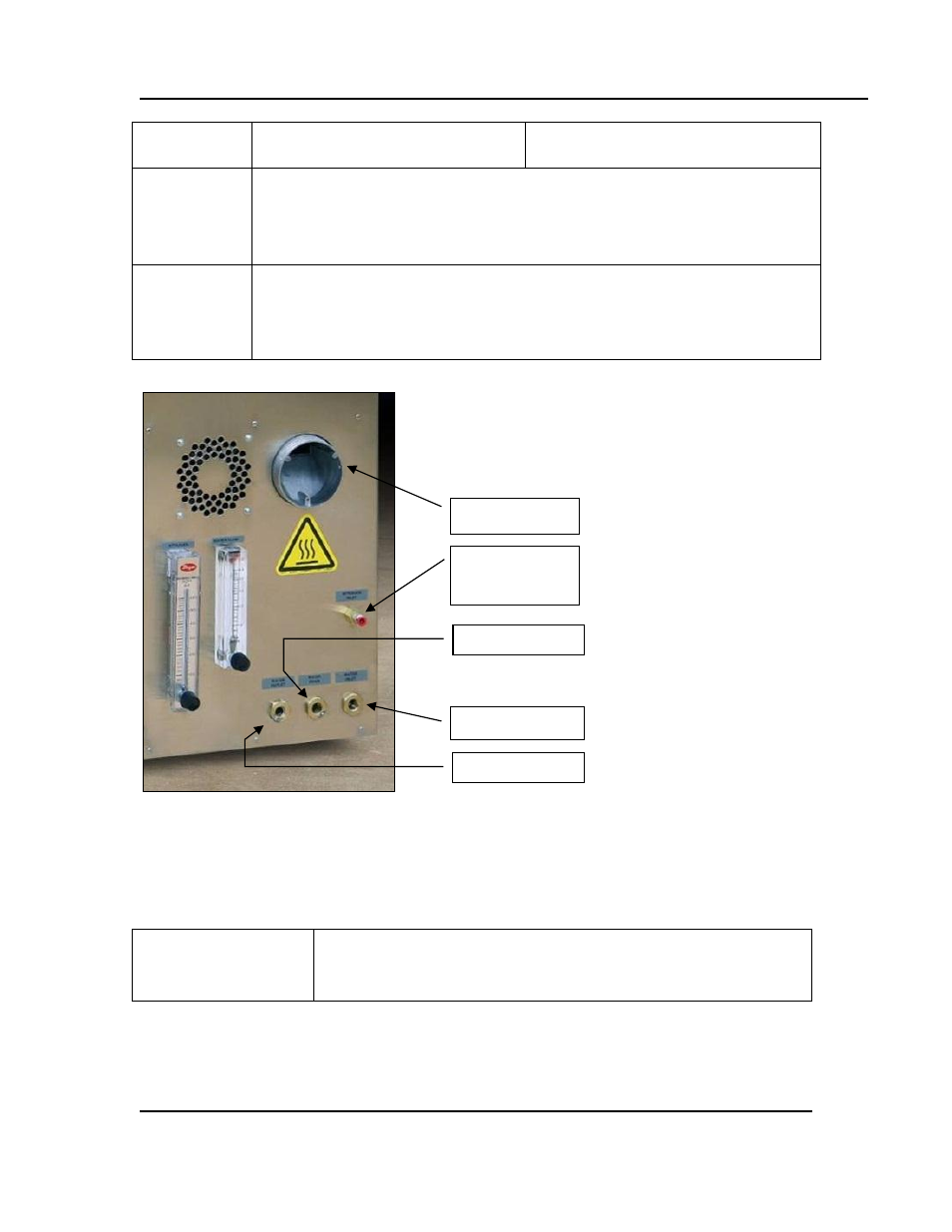
Figure 8. LCC/LCD2-14 Utility Connections.
4.2.2.1. Nitrogen With Water-Cooled Models
1. Connect nitrogen supply line to
NITROGEN INLET
on the side of the oven (Figure 8).
2. Install water connection for cooling coils to
WATER INLET
(Figure 8).Verify the valve on
the flowmeter is turned OFF, that is, fully clockwise.
Nitrogen pressure supplied should run at 70 psi (4.83 bar) but
not more than 80 psi (5.52 bar). Check for leaks.
Nitrogen/Clean
Dry Air Inlet
Water Inlet
Water Drain
Water Outlet
Exhaust