Attaching corrective weights – COATS ProRide Wheel Balancer User Manual
Page 23
Important: Always read and follow instructions.
• 19
Attaching Corrective Weights
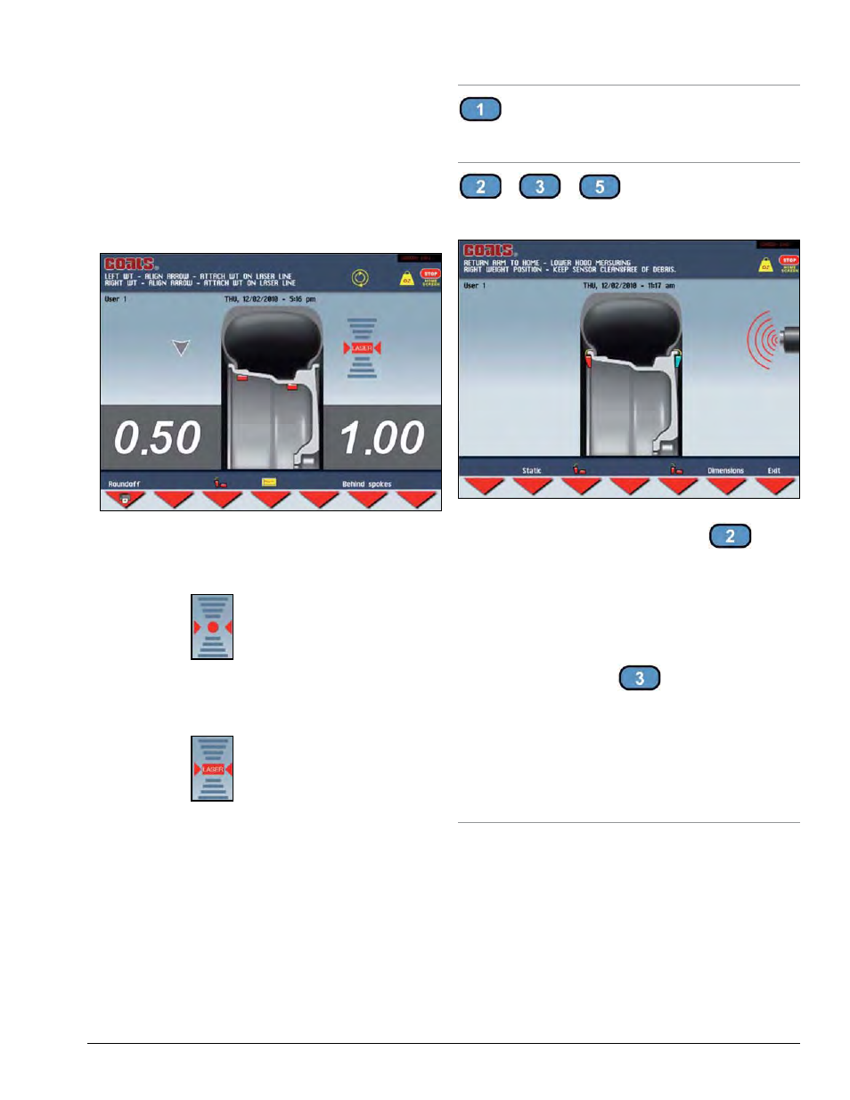
Measurement Result
After the wheel spins and out of balances are mea-
sured and displayed, the corrective weight amount
appears on the video display for inboard and outboard
weight locations. Arrows appear that are useful for posi-
tioning the corrective weight at the application point.
If the out-of-balance is less than the chosen threshold
value, - - - appears instead of the out-of-balance value
to indicate, on that particular side, that the wheel is in
tolerance.
Figure 18 - Measurement Result Screen
Laser OFF: after positioning and locking the wheel,
apply the weight vertically at 12 o’clock (top-dead-
center).
The symbol
is shown on the screen.
Laser ON: apply the clip-on weights at 12 o’clock. If
using adhesive weights, when the correction position is
reached, the laser turns on indicating the point to apply
the adhesive weight.
The symbol
is shown on the screen.
Note: If the acoustic signal is enabled, a BEEP will
signal that the wheel is in position for corrective weight
placement.
Note: If the wheel locking feature is enabled (see
MENU), the wheel is automatically held in place for
corrective weight placement.
Measurement Result Screen Options
The following buttons are enabled:
Roundoff
Press to display the residual out of balance, with an
accuracy of 0.1-ounce (0.5 g).
/
/
Correction Mode
After performing an automatic entry of wheel dimen-
sions, select to place the correction weights as required.
Figure 19 - Weight Placement Screen
To display static out of balance, press the
button
on the measurement screen (the inner side diameter is
always considered).
Note: If, when an automatic measurement is taken for
both planes, the difference between the inner and outer
diameters is greater than or equal to 2 inches, the sys-
tem sets the inboard side corrective weight. To modify
this presetting, press the
button. The outboard
side may only be “adhesive”.
Note: When the mode is changed, the out of balance
values are recalculated automatically on the basis of the
previous spin. Simultaneous display of the Static out
of balance always preset can be enabled through the
special function in Set-up (STATIC OUT OF BALANCE
DISPLAYED).