COATS ProRide Wheel Balancer User Manual
Page 21
Important: Always read and follow instructions.
• 17
• For A1 data entry, move the arm from home position
and place the offset arm up against the wheel flange
in position A1, as shown in figure 15.
• For A2 data entry, after taking the inboard measure-
ment, move the offset arm to the inner area of the
wheel; up against the rim at the outboard weight
placement location, as shown in figure 15.
Important: The A2 measurement must be at least
2-inches greater than the A1 measurement.
Figure 15 - Automatic A2 & D2 Measurement At Adhesive
Weight Location
2.
Return offset arm to home position.
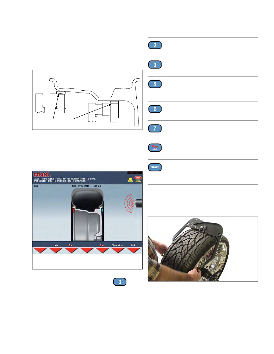
3.
Lower the hood guard to enter W wheel data
automatically.
Figure 16 - Automatic W Measurement
Note: After wheel data entry, use the
key to
select the inboard plane correction type for ALUS.
Dimension screen buttons enabled:
- automatic width measurement
- automatic ALUS wheel measurement
are:
Static / Dynamic
Toggle between Dynamic and Static balancing.
Weight Type Selection
Select either clip or adhesive weight for inboard plane.
Weight Type Selection
Only for automatic width: select either clip or adhesive
weight for outboard plane.
Dimensions
Select the manual dimension presetting screen.
Exit
Return to Result screen
Stop & Exit
Return to Home screen
Spin Wheel
When hood guard is lowered wheel spins and out of
balances are measured
Note: When manually entering W, use the plastic
calipers provided with the wheel balancer to measure
the wheel width, as shown in figure 17. Enter the W
dimension to match the measured caliper width of the
mounted rim.
Figure 17 - Caliper Placement On Wheel
Note: You must manually input wheel dimensions for
any wheel above a 24-inch diameter.
Note: On small diameter wheels, the mounting sur-
face must be a minimum 7-inch diameter.
A1
A2
Position of Adhesive
Weights
Inboard
Outboard
FUNCTION ON
INDICATOR: Sonar
“WIDTH”.