Mounting wheel on shaft, Caution – COATS ProRide Wheel Balancer User Manual
Page 18
14 •
Important: Always read and follow instructions.
Wheel Locking
Enable/disable wheel locking in the weight correction
position. Operational only on PL version balancer.
The possible options are:
OFF: disabled
ON: enabled
ALUS: enables wheel locking in position for the ALUS
correction mode only.
Laser
Enable/disable laser for adhesive weight positioning.
Note that offset arm locking will not be enabled when
laser is activated.
Special Functions Screen
Buttons enabled:
Owner Address
This information appears on the screensaver.
Operators Name
Enter up to four different machine user names. Follow
the on-screen instructions to complete the customizing.
Machine Self-test
Self-diagnostic screen is provided for easier trouble-
shooting.
Mounting Wheel On Shaft
Select the most appropriate mounting method for
the wheel you are balancing. Using the proper method
ensures secure mounting and safe balancer operation,
and prevents damage to the wheel.
On most wheels, the inner side of the wheel hub usu-
ally has the most uniform surface for wheel balancing.
Always center the wheel by the most uniform shaped
side of the hub to achieve the most accurate balance.
Regardless of mounting type, on standard units,
always make sure that the wheel is forced firmly against
the shaft faceplate and that the hub nut engages the
threaded shaft for at least four complete turns. To assist
in centering the wheel properly, rotate the wheel and
the shaft while tightening the hub nut.
CAUTION
Failure to tighten the hub nut properly may
result in the wheel dismounting, causing
personal injury and property damage.
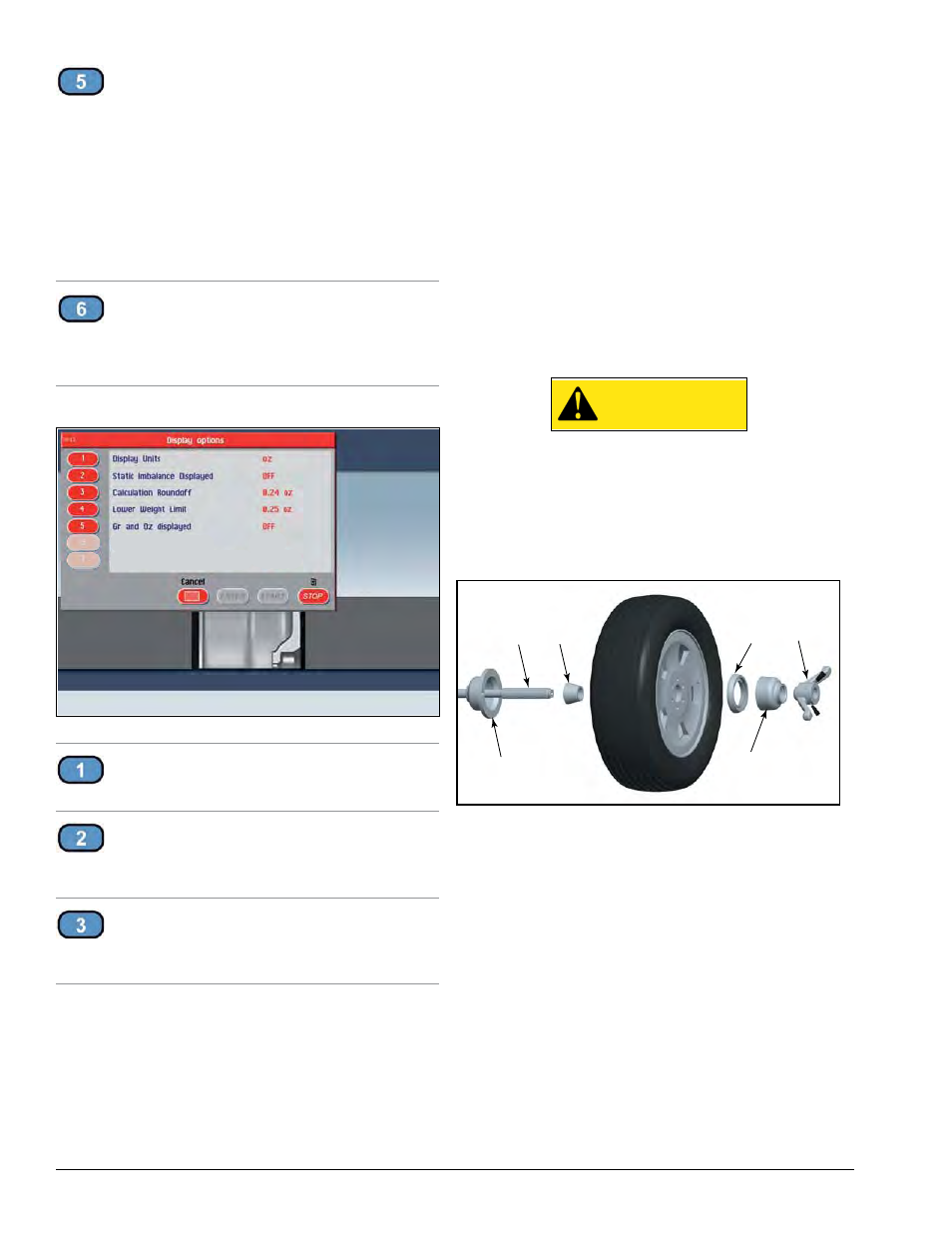
Standard Back Cone Mounting
Most original equipment and steel wheels can be
mounted properly using this method. The wheel is
centered on a cone from the inner side of the hub.
Figure 7 - Standard Back Cone Mounting
1.
Select the cone that best fits the center hole in the
wheel. Slide the cone onto the shaft with the large end
towards the faceplate.
2.
Lift wheel onto the shaft and center it on the cone.
3.
Attach the pressure cup to the hub nut and install
the assembly onto the shaft. Tighten securely.
Note: Use a nylon spacer (no mar ring) to protect
custom wheel finishes.
4.
Thread the hub nut onto the shaft, and tighten it
against the wheel. The wheel must be forced firmly
against the faceplate. The hub nut must engage the
threads for at least four full turns.
Note: If the hub nut will not tighten completely, use
the front cone mounting method.
Shaft
Cone
Pressure
Cup
Protective
Ring
Hub Nut
Face Plate