COATS 6200HS Truck Wheel Balancer User Manual
Page 11
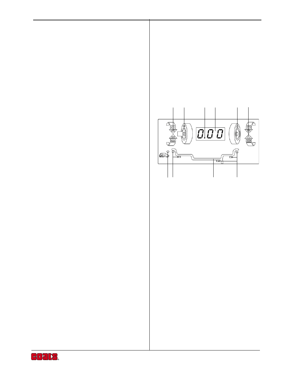
Operation Guide
5
2
4a
4b
3a
3b
5
6
6
7
1
Balancer Display
The display combines solid-state electronics and
graphical design to provide powerful visual presentation
and durability.
The display indicates the amount and position of
weights, wheel dimensions, operating modes and error
conditions.
1. Numeric Display
Displays weights in grams or ounces after a spin cycle,
when the wheel is rotated to the inner or outer Top-
Dead-Center position. Displays wheel dimensions
(diameter, width, offset) in inches or millimeters during
wheel data entry. Displays ‘EEE’ to report an error.
2. Decimal Point
Illuminated constantly when ounces are selected as
weight units.
3. Weight Position Indicators
Illuminated sequentially as the wheel is rotated and the
correct position for weight placement is approached.
This applies to both inner (3a) and outer (3b) weight
positions.
4. Top-Dead-Center Indicators
Illuminated when the correct position for attaching the
weight at Top-Dead-Center (TDC) is reached. There are
separate indicators for the inner (4a) and outer (4b) TDC
positions.
5. Rim Profile
Graphical rim profile to illustrate the Weight Mode in
operation.
6. Weight Mode Indicators
Illuminated Clip-On Weight (green, circular) and Stick-
On Weight (yellow, rectangular) indicators to
correspond to the Weight Mode selected.
7. Car Indicator
When the rim diameter is set at 17" or less the Car
Indicator will light. This allows wheels to be Fine
balanced to an accuracy of 2 grams (0.10 ounce). Refer
also to the
Weight Location Modes and Automatic
Calibration sections of this manual for further details.