Maintenance, Reassembly/seal replacement, Figure 4-19: steer cylinder – Snorkel A38E-sn006001+ User Manual
Page 56: Installation, Figure 4-20: master levelling cylinder
Maintenance
Section
4-24
A38E Work Platform
4.17
CLEANING AND INSPECTION
1.
Clean all metal parts in solvent and blow dry
with filtered compressed air.
2.
Check all threaded parts for stripped or
damaged threads.
3.
Check the bearing surfaces inside of the
headcap, outer edge surface of the rod & piston
assembly or inside of the cylinder barrel and the
shaft for signs of scoring, pits, excessive wear
or polishing. Scratches or pits deep enough to
catch a fingernail are unacceptable. Polishing is
a sign of uneven loading and if sufficiently
polished the affected parts should be replaced.
4.
Replace any parts or seals found to be
unserviceable.
REASSEMBLY/SEAL REPLACEMENT
1.
Lubricate and install new rod seal, rod wiper
and static seal on the headcap.
NOTE: Multi-purpose lubricant should be used.
2.
Install a new piston seal on the piston.
3.
Install the headcap on one end of the cylinder
barrel.
4.
Lubricate the piston seal and install the rod &
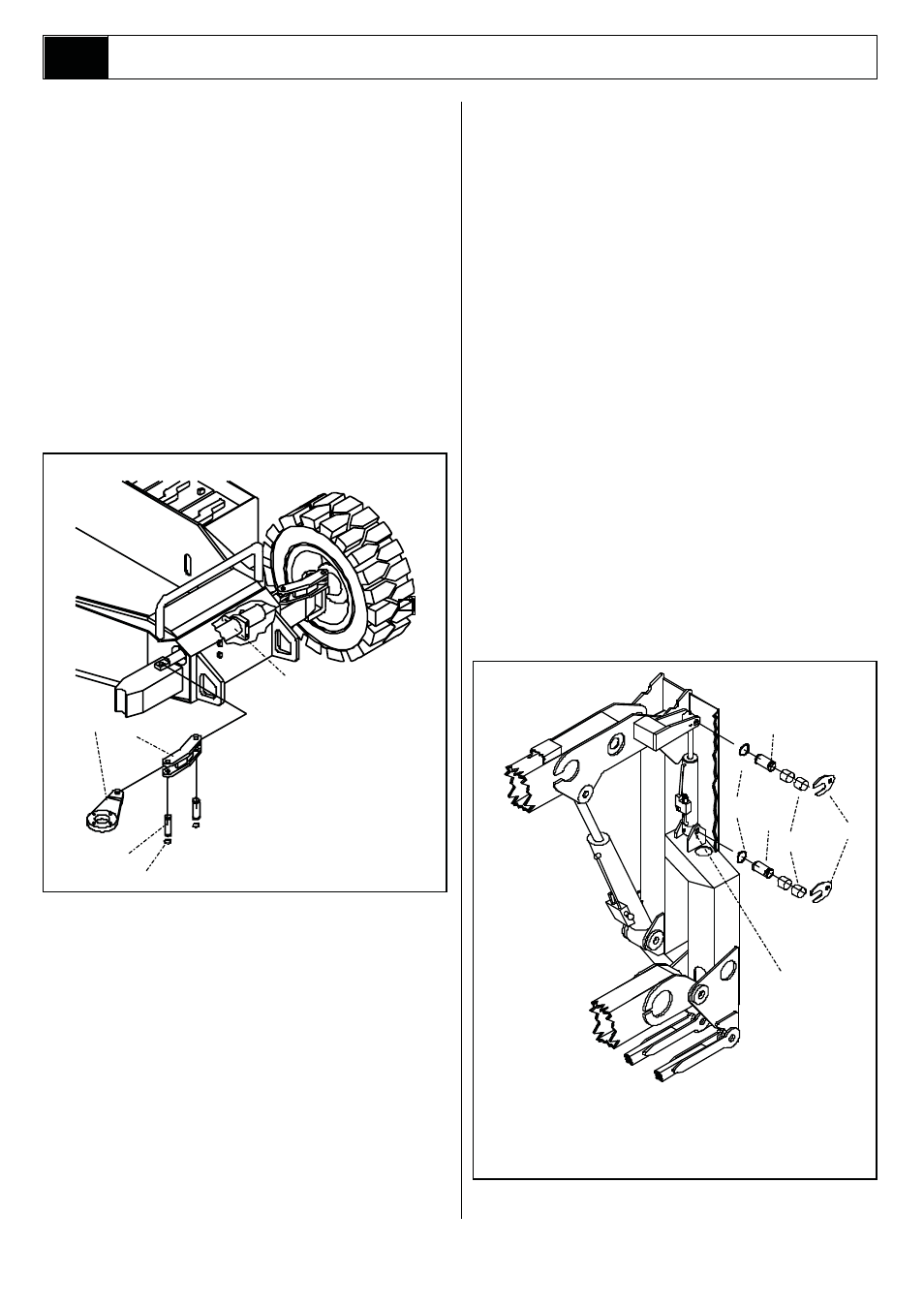
Figure 4-19: Steer Cylinder
piston assembly in the barrel tube.
6.
Thread the headcap onto the free end of the
barrel tube and hand tighten, then turn 1/4 turn
further.
INSTALLATION
NOTE: Before installing the Steering Cylinder check
cylinder pins and bearings for wear and replace if
necessary.
1.
While supporting the cylinder replace the four
washers and bolts at the front panel of the
A38E’s chassis.
2.
Move the steering arm so that the holes for
positioning the pins are correct. Install each
of the steering pivot pins and ensure that the
circlips are attached properly.
NOTE: Take care in aligning the holes so that
the pin can be pushed in by hand. If holes are
not properly aligned and the pin is forced in, the
bearings will be damaged.
Torque these four bolts to 90 Nm (66 ft. lbs).
3.
Reconnect the hydraulic hoses.
4.
Test system operation by carrying out a ‘figure
of eight’ driving pattern for 5 cycles. This should
be sufficient to prove proper function.
Figure 4-20: Master Levelling Cylinder
1.
Steering Cylinder
2.
Steering Link Arm
3.
Torque Arms
4.
Steering Pivot Pins
5.
Circlip
3
2
4
5
1
1.
Bushings
2.
Circlip
3.
Barrel End Pivot Pin
2
3
5
4
6
4.
Master Levelling
Cylinder
5.
Pin Lock Plate
6.
Rod End Pivot Pin
1
Note: During seal replacement do not use sharp
edged tools to avoid cutting the seals, and allow
at least one hour for the seals to elastically
restore to their original shape before assembly.