Maintenance, Removal, Disassembly (refer to figure 4-16) – Snorkel A38E-sn006001+ User Manual
Page 53: Cleaning and inspection, Reassembly/seal replacement
Maintenance
Section
4-21
A38E Work Platform
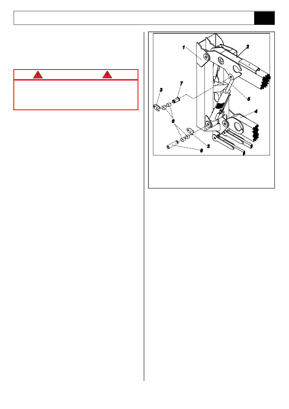
Figure 4-17: Upper Lift Cylinder
1.
Second Post
2.
Upper Boom
3.
Pin Lock Plate
4.
Lower Boom
5.
Upper Lift Cylinder
6.
Bushings
7.
Rod End Pivot Pin
8.
Barrel End Pivot Pin
2
4.15
4.15 Upper Lift Cylinder
(Figure 4-17)
REMOVAL
The Upper Lift Cylinder is heavy, so utilise
appropriate lifting equipment to support the
unit before removing pins.
1.
Ensure that the A38E is on firm level ground,
the Elevating Assembly is completely stowed,
the Keyswitch is to the ‘OFF’ position and the
Emergency Stop Button is pressed.
2.
Provide a suitable container to collect the
hydraulic fluid, then disconnect the hydraulic
hoses. Immediately plug hoses to prevent
foreign material from entering.
3.
Remove securing bolts and the pin lock plates
from the cylinder pins.
4.
Support rod end of cylinder and remove rod end
pivot pin. Let cylinder down to hang freely.
5.
Support the cylinder so that the barrel end
cylinder pin can be removed, then remove the
cylinder from the machine.
6.
Move the cylinder to a prepared work area. It is
important that clean assembly practices are
observed as seals and other hydraulic cylinder
components are highly sensitive to
contamination.
DISASSEMBLY (Refer to Figure 4-16)
1.
Unscrew the headcap and withdraw the rod and
piston assembly from the barrel tube.
2.
Unscrew the piston nut and remove piston and
headcap from the cylinder rod.
3.
Remove the piston static O-ring from the
cylinder rod.
4.
Remove the piston seal from the piston.
5.
Remove the rod seal, rod wiper and static seal
from the headcap.
6.
Care should be taken to save the O-ring and all
other seals for reassembly, if they have been
deemed serviceable following the cleaning and
inspection phase of maintenance.
CLEANING AND INSPECTION
1.
Clean all metal parts in solvent and blow dry
with filtered compressed air.
2.
Check all threaded parts for stripped or
damaged threads.
3.
Check the bearing surfaces inside of the
headcap, outer edge surface of the piston,
inside of the cylinder barrel and the shaft for
signs of scoring, pits, excessive wear or
polishing. Scratches or pits deep enough to
catch a fingernail are unacceptable. Polishing is
a sign of uneven loading and if sufficiently
polished the affected parts should be replaced.
4.
Replace any parts or seals found to be
unserviceable.
REASSEMBLY/SEAL REPLACEMENT
1.
Lubricate and install new rod seal, rod wiper
and static seal on the headcap.
NOTE: Multi-purpose lubricant should be used.
2.
Install a new piston seal on the piston.
3.
Install the headcap on the cylinder from the
piston end.
4.
Install the piston, piston nut and a new piston
static O-ring on the cylinder rod. Screw nut to
1
5
4
6
3
8
7
3
Note: During seal replacement do not use sharp
edged tools to avoid cutting the seals, and allow
at least one hour for the seals to elastically
restore to their original shape before assembly.
CAUTION