Maintenance, 6 maintenance on elevating assembly (figure 4-6) – Snorkel A38E-sn006001+ User Manual
Page 39
Maintenance
Section
4-7
A38E Work Platform
4.6
4.6 Maintenance on Elevating
Assembly (Figure 4-6)
The only time the Elevating Assembly needs to be
elevated is to allow service work to be carried out on
the lower parts of the Elevating Assembly, the Lower
Lift Cylinder or the Slewing mechanisms.
All other work (Bearings, Cylinders, Booms & Tension
Bars) can and must be performed with the Elevating
Assembly in the stowed position.
BEFORE entering Elevating Assembly, to
perform maintenance on the Work Platform
while elevated, ensure that Elevating
Assembly is properly supported by suitable
cranage of adequate capacity.
(Recommended 1 tonne capacity crane and
sling.)
INSTALLATION OF ELEVATING
ASSEMBLY SUPPORT
1. Park the work platform on firm level ground.
2. Verify Platform Emergency Stop Switch is ON.
3. Hold the Chassis/Platform Selector Switch on the
Lower Control Box to the ‘Chassis’ position.
4. Select Lower Control Boom 1 Switch and
elevate until the lower boom is slightly above
horizontal.
5. Place a sling of 1 Tonne load capacity at the end of
the lower boom and second post. Ensure sling is
secured so that it will not slip up along the boom.
6. Gradually lower the platform until
Lower Boom is supported by the sling.
REMOVAL OF ELEVATING
ASSEMBLY SUPPORT
1. Select Lower Control Boom 1 Switch
and gradually raise the platform until the
sling can be removed.
2. Remove the sling.
3. Completely lower platform.
4. Turn Key Switch to “OFF”
SLEW CROSS-LINE RELIEF VALVES
1.
Repeat steps 1-3 as outlined above
2.
Loosen Locknuts on both cross-line relief
valves and turn adjusting screws anticlockwise
two full turns.
3.
Operate slew function from lower controls and
rotate the Elevating Assembly until the slew
stop prevents further rotation.
4.
Slowly turn the cross-line relief valve adjusting
screw clockwise using a 4 mm Allen key until
the pressure gauge reads 50 Bar (725 p.s.i.)
pressure.
5.
Now operate the slew function in the opposite
direction through approximately 360
o
until the
Slew Stop prevents further rotation.
6.
Slowly turn the remaining cross-line relief valve
adjusting screw clockwise until the pressure
gauge reads 50 Bar (725 p.s.i.) pressure.
7.
Tighten the locknuts on both cross-line relief
valves while holding the adjusting screws in
position.
Figure 4-5: Setting Cross-Line Relief
Pressures
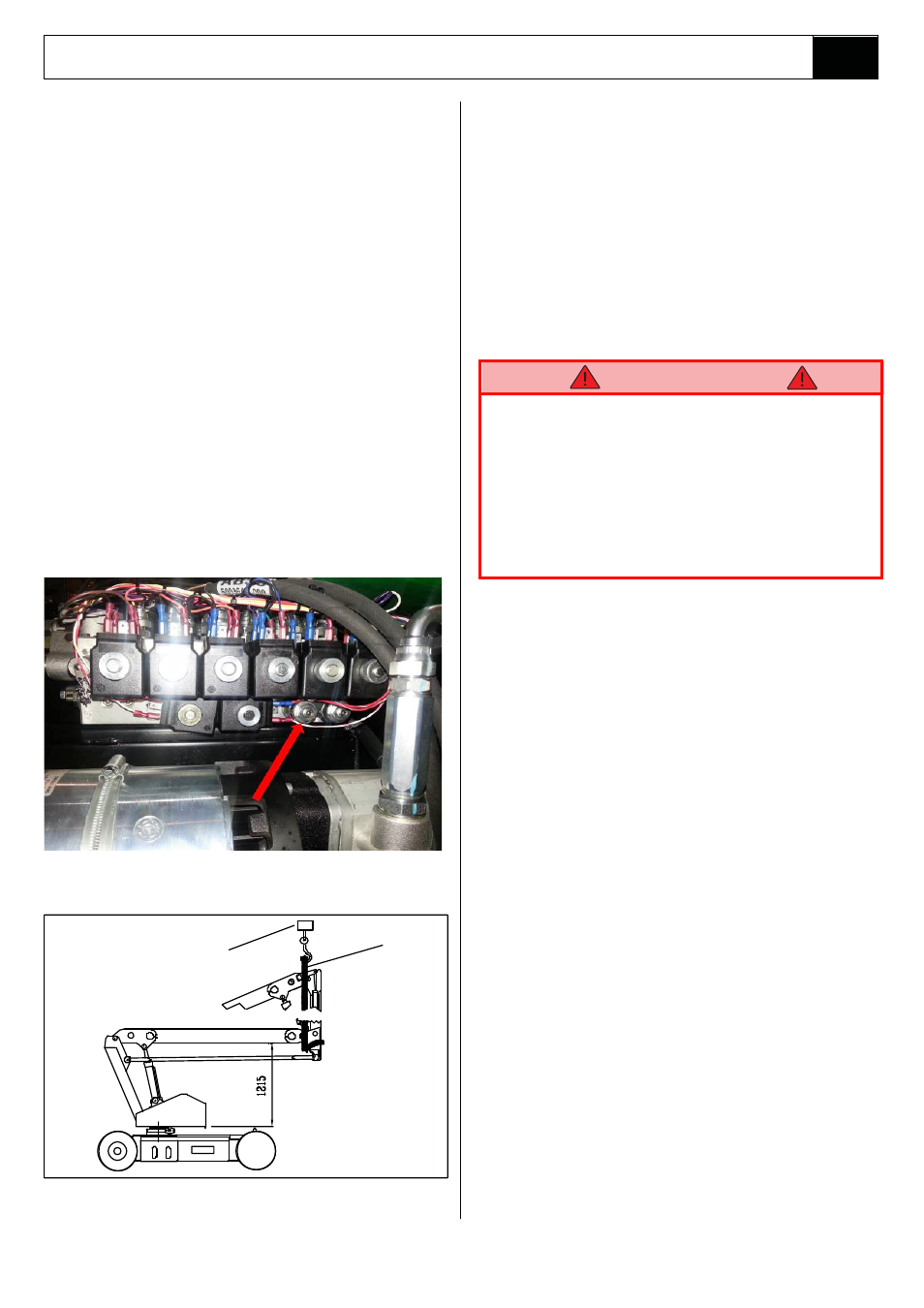
Figure 4-6: Supporting Elevating Assy.
1 Tonne Capacity
Crane/Winch
Sling
W A R N I N G