Maintenance, 8 a38e work platform, 7 boom rest limit switch – Snorkel A38E-sn006001+ User Manual
Page 40: Tilt sensor
Maintenance
Section
4-8
A38E Work Platform
4.7 Switch Adjustments
(Figure 4-7 & 4-8)
4.7
BOOM REST LIMIT SWITCH
Function: This limit switch is activated when the
Elevating Assembly is fully stowed and
the upper boom is sitting in the boom rest. The Boom
Rest is located on the side of the First Post on the
A38E Work Platform. The high speed drive can only
be operated when this switch is activated. When the
boom leaves the boom rest the Normally Open con-
tacts of the limit switch open and power is cut to the
high speed drive function.
Location: The switch is located on the side of the
First
(see fig 4-8)
Post on the Boom Rest Weldment.
Adjustment:The switch should be activated when the
boom sits in the boom rest. The lever is
adjustable and should be adjusted so that the
switch’s activation/deactivation point occurs just as
Boom 2 leaves the Boom Rest. To adjust the switch
loosen the lever clamping nut and rotate the lever.
Tighten the lever clamping nut. The switch should
periodically be checked for freedom of movement and
be kept clean from dirt and other contaminants that
might affect its free movement.
TILT SENSOR
Function: This limit switch is activated when the
internal sensor in the ‘Tilt Sensor’ is tilted
3
°
or more (factory set at this value). When the Tilt
Sensor activates the elevating and telescope extend
functions will be locked out and an audible warning
alarm will sound. It will activate if the Chassis tilts 3
°
in any direction.
The Tilt Sensor is incorporated in the GP400 control
module.
S
ETTING
T
HE
T
ILT
S
ENSOR
T
O
Z
ERO
If the EZ230 control modual is replaced and/of moved within the
machine for any reason the tilt sensor must be reset for zero°
using the following procedure. Failure to do so could result in serious
injury or death.
To follow this procedure you need to switch the Ezcal
display in the Upper Control Box into “Calibration mode”.
1. Place the machine on a firm level surface , ≤ 0.25 °
2 Use a Gauge to confirm that the front and rear of the
chassis are level to within +/- 0.25 ° in both directions
3. Switch the machine on, press and hold Esc for 5 seconds
.
s
r
a
e
p
p
A
”
u
n
e
M
t
fi
l
z
E
“
li
t
n
u
4. Scroll to access level.(Enter)
5.
Enter code 2222 for access level 2 .(Enter)
6. Scroll to setups.(Enter)
7. Scroll to tilt setups . (Enter)
8. Calibrate level. (Enter)
9. Enter for yes.
To confirm calibration has worked switch the machine of then
back on again.
10. Scroll to Diagnostics. (Enter)
11. System. (Enter)
12. Scroll to tilt, both readings should be below 0.2 ° if not
repeat from 3.
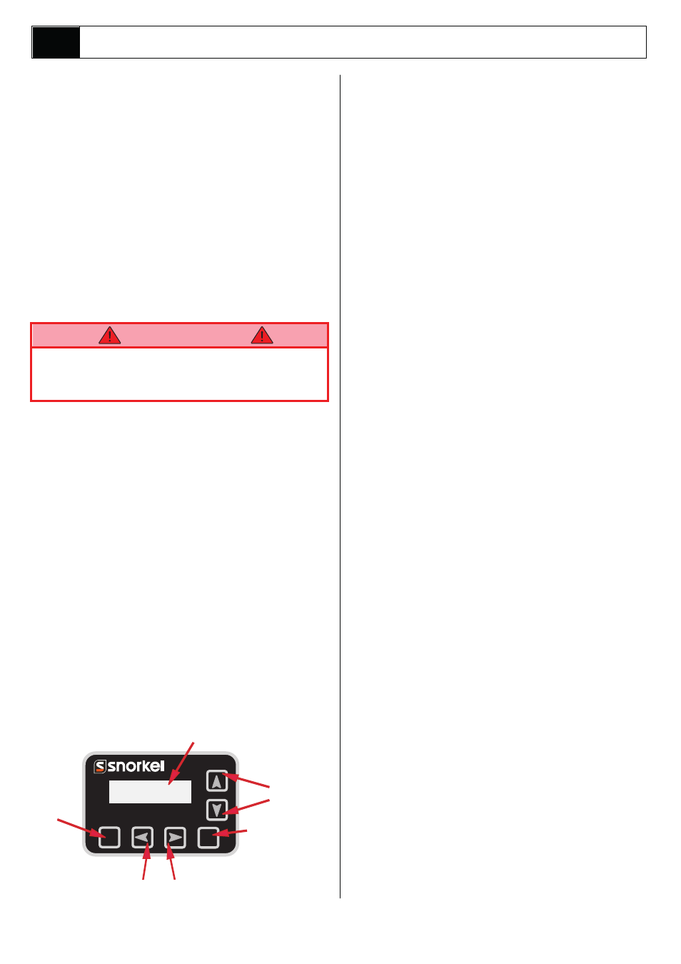
ESC
ENTER
Esc to leave
Sub-Menu
without saving.
Display
Enter to Save
Entry
Scroll
Left/Right
Change Entry
Up / Down
W A R N I N G