AEM 30-6905 Universal Programmable EMS-4 User Manual
Page 23
Page 23 of 279 EMS-4 Install and Tuning Guide_Rev 1.6
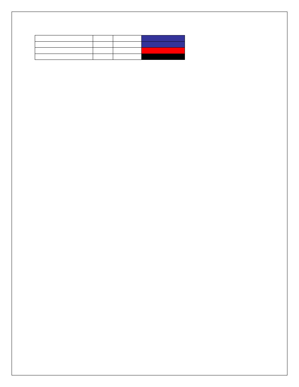
Coil 3 Output
22
Dk Blue
IGN 3
Coil 4 Output
22
Dk Blue
IGN 4
Fused Coil Power
14
Red
COIL PWR
Coil Ground
14
Black
PWR GND
Warning! - The ignition outputs from the EMS-4 are not designed to trigger an ignition
coil directly. Connecting them to a coil that does not contain a built-in driver will damage
the EMS-4. Coils without built-in drivers typically have only two pins on the connector.
Coils with built-in drivers typically have 4 or more pins on the connector. If you are not
sure what kind of ignition coils you have, contact AEM tech support for help.
IGN 1
– Connect to 1
st
coil driver to fire.
IGN 2
– Connect to 2
nd
coil driver to fire.
IGN 3
– Connect to 3
rd
coil driver to fire.
IGN 4
– Connect to 4
th
coil driver to fire.
COIL PWR
– Fused coil power. Splice required number of power leads and distribute to each
coil.
PWR GND
– Ignition power ground.
AEM Kit P/N 30-2840 (Optional)
Four Channel Coil Driver is custom manufactured to AEM‟s
specifications by HÜCO Electronic GmbH in their ISO 9001 facility in Germany. It has been
specially designed by AEM for driving the high power dwell controlled ignition coils commonly
found on performance engines.
The 30-2840 Kit contains:
Four Channel Coil Driver
Five Pin Mating Connector
Four Pin Mating Connector
10 Terminals & Wire seals (one extra of each as a precaution)
Mounting hardware
Thermal Grease