Bryant 312AAV User Manual
Page 9
If Coil Assembly Part No. CD5 or CK5 or Coil Box Part No.
KCAKC is used, install as shown in Fig. 13.
NOTE: Remove the furnace perforated supply-air duct flanges
when they interfere with mating flanges on the coil on downflow
subbase. To remove the supply-air duct flange, use wide duct
pliers or duct flange tool to bend flange back and forth until it
breaks off. Be careful of sharp edges. (See Fig. 14.)
WARNING: Do not bend duct flanges inward. This will
affect airflow across heat exchangers and may cause limit
cycling or premature heat exchanger failure. Remove
duct flange completely or bend it inward a minimum of
210° as shown in Fig. 14.
IV. HORIZONTAL ATTIC INSTALLATION
WARNING: Do not install the furnace on its back;
safety control operation will be adversely affected. Never
connect return-air ducts to the sides or back of the
furnace. Failure to follow this warning could result in fire,
personal injury, or death.
The furnace can be installed horizontally on either the left-hand
(LH) or right-hand (RH) side. A typical attic installation is shown
in Fig. 17.
A. Construct a Working Platform
Construct working platform on location where all required furnace
clearances are met. (See Fig. 2 and 17.)
B. Install Furnace
1. Position furnace in desired location.
2. Connect gas supply pipe. See Fig. 17 for typical piping
entry.
3. Connect supply- and return-air ducts with filter media
cabinet per Step 6.
4. Install 24- X 24-in. sheet metal shield on platform in front
of louvered control panel as shown in Fig. 17.
V. INSTALLATION IN HORIZONTAL CRAWLSPACE AP-
PLICATIONS
These furnaces can be installed horizontally in either horizontal
left or right discharge position. In a crawlspace, furnace can either
be hung from floor joist or installed on suitable blocks or pad. (See
Fig. 16). Furnace can be suspended from each corner by hanger
bolts and angle iron supports. (See Fig. 15.) Cut hanger bolts (4
each 3/8-in. all-thread rod) to desired length. Use 1 X 3/8-in. flat
washers, 3/8-in. lockwashers, and 3/8-in. nuts on hanger rods as
shown in Fig. 15.
CAUTION: The entire length of the furnace MUST be
supported when furnace is used in a horizontal position.
When suspended, bottom brace supports sides and center
blower shelf. When unit is supported from the ground,
blocks or pad should support sides and center blower
shelf area.
VI. MEDIA CABINET (PN 325887–701) AND FILTER AR-
RANGEMENT
Center media cabinet on furnace return-air inlet. If flush fit
required with media cabinet to back of furnace casing, a field
supplied patch plate is required to seal gap at front edge of furnace
and media cabinet. Insert filter (supplied with furnace) into media
cabinet.
WARNING: Never operate a furnace without a filter or
with filter access door removed. Failure to follow this
warning could result in fire, personal injury, or death.
VII. GAS PIPING
Gas piping must be installed in accordance with national and local
codes. Refer to current edition of NFGC in the U.S.
Canadian installations must be made in accordance with NSCNG-
PIC and all authorities having jurisdiction.
Gas supply line should be a separate line running directly from
meter to furnace, if possible.
Refer to Table 5 for recommended gas pipe sizing. Risers must be
used to connect to furnace and to meter. Support all gas piping
with appropriate straps, hangers, etc. Use a minimum of 1 hanger
every 6 ft. Joint compound (pipe dope) should be applied sparingly
and only to male threads of joints. Pipe dope must be resistant to
the action of propane gas.
CAUTION: If a flexible connector is required or al-
lowed by the authority having jurisdiction, black iron
pipe shall be installed at the gas valve and extend a
minimum of 2 in. outside the furnace casing.
CAUTION: Connect gas pipe to furnace using a backup
wrench to avoid damaging gas controls.
WARNING: Never purge a gas line into a combustion
chamber. Never use matches, candles, flame, or other
sources of ignition for purpose of checking leakage. Use
a soap-and-water solution to check for leakage. A failure
to follow this warning could result in fire, explosion,
personal injury, or death.
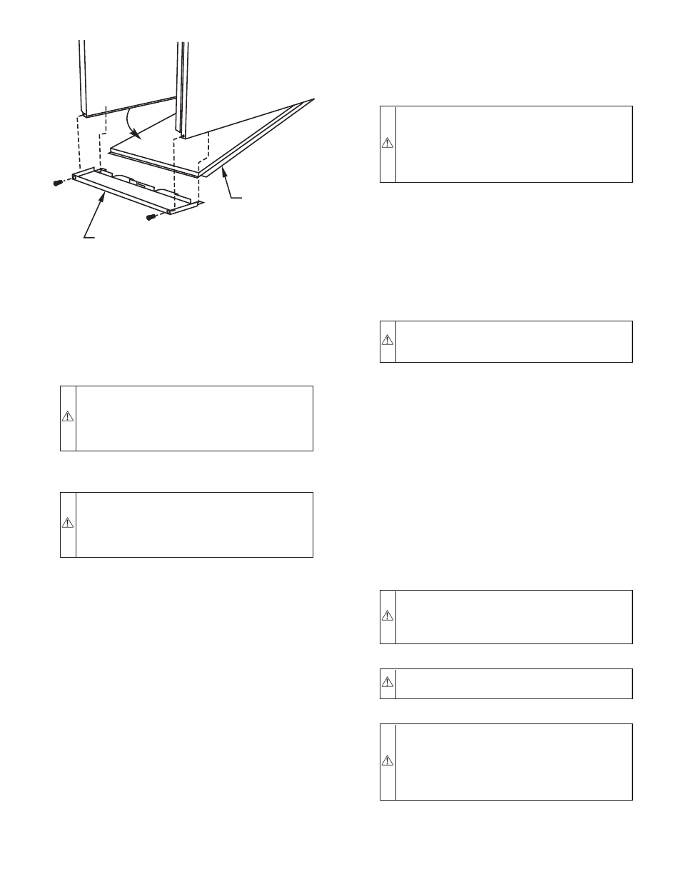
Fig. 10–Removing Bottom Closure Panel
A93047
BOTTOM
CLOSURE
PANEL
FRONT FILLER
PANEL
—9—