Bryant 312AAV User Manual
Page 16
b. Igniter Warm-Up- At the end of the prepurge period,
the Hot-Surface Igniter HSI is energized for a 17-second
igniter warm-up period.
c. Trial-for-Ignition Sequence- When the igniter
warm-up period is completed the main gas valve relay
contacts GVR-1 and -2 close to energize the gas valve
solenoid GV-M, the gas valve opens, and 24 vac power
is supplied for a field-installed humidifier at the HUM
terminal. The gas valve solenoid GV-M permits gas flow
to the burners where it is ignited. After 5 seconds, the
igniter HSI is de-energized and a 2-second Flame-
Proving period begins.
If the furnace control CPU selects high-heat operation,
the high-heat gas valve solenoid GV-HI is also ener-
gized.
d. Flame-Proving- When the burner flame is proved at the
flame-proving sensor electrode FSE, the furnace control
CPU begins the blower-ON delay period and continues
to hold the gas valve GV-M open. If the burner flame is
not proved within two seconds, the control CPU will
close the gas valve GV-M, and the control CPU will
repeat the ignition sequence for up to three more
Trials-For-Ignition before going to Ignition-Lockout.
Lockout will be reset automatically after three hours, by
momentarily interrupting 115 vac power to the furnace,
or by interrupting 24 vac power at SEC1 or SEC2 to the
furnace control CPU (not at W/W1, G, R, etc.).
If flame is proved when flame should not be present, the
furnace control CPU will lock out of Gas-Heating mode
and operate the inducer motor IDM on high speed until
flame is no longer proved.
If flame is proved when flame should not be present, the
furnace control CPU will lock out of Gas-Heating mode
and operate the inducer motor IDM until flame is no
longer proved.
e. Blower-ON Delay-If the burner flame is proven the
blower-ON delay for low-heat and high-heat are as
follows:
Low-Heat - 45 seconds after the gas valve GV-M is
energized the blower motor BLWM is energized at LO
HEAT speed.
High-Heat - 25 seconds after the gas valve GV-M is
energized the BLWM is energized at HI HEAT speed.
Simultaneously, the electronic air cleaner terminal
EAC-1 is energized and remains energized as long as the
blower motor BLWM is energized.
f. Switching from Low-to High-Heat-If the furnace con-
trol CPU switches from low-heat to high-heat, the
furnace control CPU will switch the inducer motor IDM
speed from low to high. The high-heat pressure switch
relay HPSR is de-energized to close the NC contact.
When sufficient pressure is available the high-heat pres-
sure switch HPS closes, and the high-heat gas valve
solenoid GV-HI is energized. The blower motor BLWM
will switch to HI HEAT speed five seconds after the
furnace control CPU switches from low-heat to high-
heat.
g. Switching from High- to Low-Heat-The furnace con-
trol CPU will not switch from high-heat to low-heat
while the thermostat R-to-W circuit is closed when using
a single-stage thermostat.
h. Blower-OFF Delay- When the thermostat is satisfied,
the R-to-W circuit is opened, de-energizing the gas valve
GV-M, stopping gas flow to the burners, and de-
energizing the humidifier terminal HUM. The inducer
motor IDM will remain energized for a 5-second post-
purge period. The blower motor BLWM and air cleaner
terminal EAC-1 will remain energized for 90, 120, 150,
or 180 seconds (depending on selection at blower-OFF
delay switches). The furnace control CPU is factory-set
for a 120-second blower-OFF delay.
2. Two-Stage Thermostat and Two-Stage Heating
(See Fig. 30 for thermostat connections)
The wall thermostat
″calls for heat″, closing the R-to-W1
circuit for low-heat or closing the R-to-W1-and-W2 circuits
for high-heat. The furnace control performs a self-check,
verifies the low-heat and high-heat pressure switch contacts
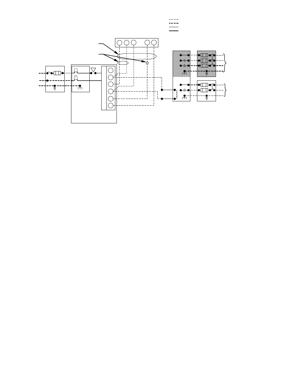
Fig. 21–Heating and Cooling Application Wiring Diagram with 1–Stage Thermostat
A95236
115-VOLT FIELD-
SUPPLIED
FUSED
DISCONNECT
JUNCTION
BOX
CONTROL
BOX
24-VOLT
TERMINAL
BLOCK
THREE-WIRE
HEATING-
ONLY
FIVE
WIRE
NOTE 2
NOTE 1
1-STAGE
THERMOSTAT
TERMINALS
FIELD-SUPPLIED
FUSED DISCONNECT
CONDENSING
UNIT
FURNACE
COM
R
W
C
Y
R
G
GND
GND
FIELD 24-VOLT WIRING
FIELD 115-, 208/230-, 460-VOLT WIRING
FACTORY 24-VOLT WIRING
FACTORY 115-VOLT WIRING
Connect Y/Y2-terminal as shown for proper operation.
Some thermostats require a "C" terminal connection as shown.
If any of the original wire, as supplied, must be replaced, use
same type or equivalent wire.
208/230- OR
460-VOLT
THREE
PHASE
208/230-
VOLT
SINGLE
PHASE
WHT
BLK
WHT
BLK
W/W1
W2
Y/Y2
G
NOTES: 1.
2.
3.
—16—