Bryant 312AAV User Manual
Page 15
the low-heat and high-heat pressure switch contacts LPS
and HPS are open, and starts the inducer motor IDM in
high-speed.
NOTE: The low-heat only switch LHT selects either the low-heat
only operation mode when ON, (see item 2. below) or the adaptive
heating mode when OFF in response to a call for heat. (See Fig.
22.) Table 7 and 8show the dipswitch setup information. When the
W2 thermostat terminal is energized it will always cause high-heat
operation when the R-to-W circuit is closed, regardless of the
setting of the low-heat only switch.
a. Inducer Prepurge Period- If the furnace control CPU
selects low-heat operation the inducer motor IDM comes
up to speed, the low-heat pressure switch LPS closes, the
inducer motor IDM switches to low-speed, and the
furnace control CPU begins a 15-second prepurge pe-
riod. If the low-heat pressure switch LPS fails to remain
closed the inducer motor IDM will switch back to
high-speed. After the low-heat pressure switch re-closes
the furnace control CPU will begin a 15-second prepurge
period, and continue to run the inducer motor IDM at
high-speed for the low-heat cycle while flashing status
code 32.
If the furnace control CPU selects high-heat operation,
the inducer motor IDM remains running at high-speed,
and the high-heat pressure switch relay HPSR is de-
energized to close the NC contact. When sufficient
pressure is available the high-heat pressure switch HPS
closes, and the high-heat gas valve solenoid GV-HI is
energized. The furnace control CPU begins a 15-second
prepurge period after the low-heat pressure switch LPS
closes. If the high-heat pressure switch HPS fails to close
and the low-heat pressure switch LPS closes, the furnace
will operate at low-heat gas flow rate until the high-heat
pressure switch closes for a maximum of 2 minutes after
ignition, after which a normal shutdown occurs and the
furnace reinstates the heating startup sequence.
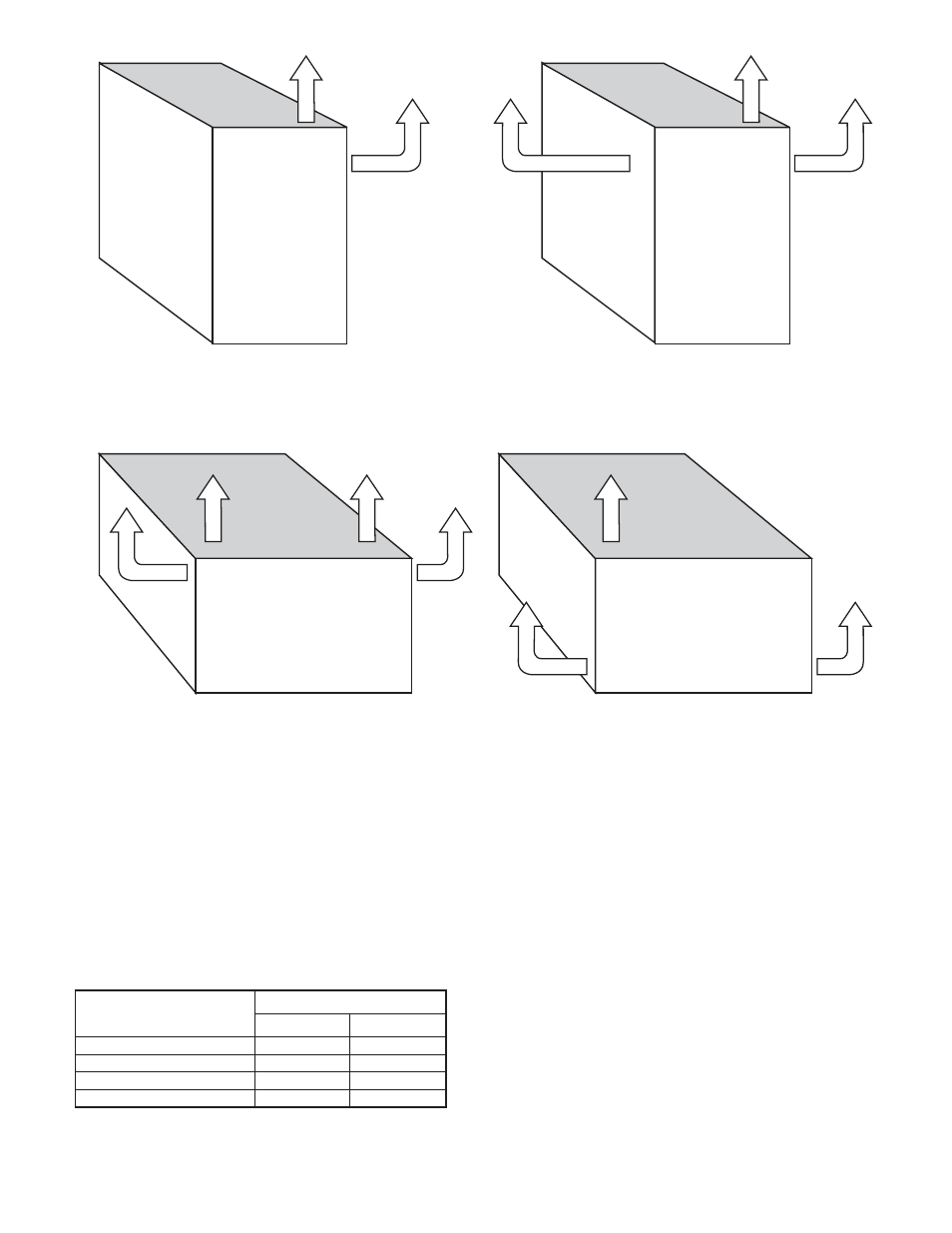
Fig. 20–Vent Orientation
A00345
Front
Horizontal
Right
Front
Horizontal
Left
Front
Upflow
Front
Downflow
TABLE 7-BLOWER OFF DELAY SETUP SWITCH (SW)
POSITION
DESIRED HEATING
MODE BLOWER-OFF
DELAY (SEC)
SETUP SWITCH
SW-2
SW-3
90
OFF
OFF
120
OFF
ON
150
ON
OFF
180
ON
ON
—15—