Bryant 312AAV User Manual
Page 7
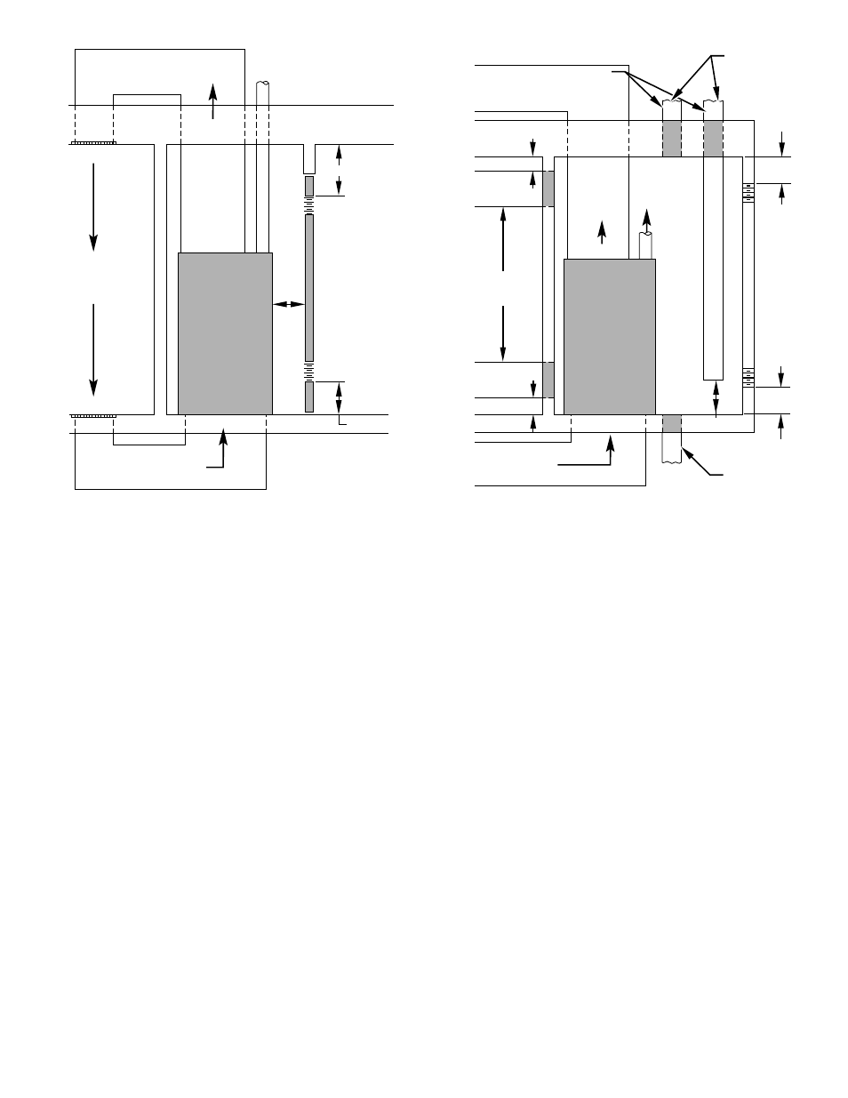
per 3000 Btuh of the total input for all equipment within
the confined space and not less than the sum of the areas
of all vent connectors in the confined space. Equipment
clearances to the structure shall be at least 1 in. from the
sides and back and 6 in. from the front of the appliances.
See Table 2 and Fig. 8.
When ducts are used, they must be of the same cross sectional area
as the free area of the openings to which they connect. The
minimum dimension of ducts must not be less than 3 in.
III. AIR DUCTS
A. General Requirements
The duct system should be designed and sized according to
accepted national standards such as those published by: Air
Conditioning Contractors Association (ACCA), Sheet Metal and
Air Conditioning Contractors National Association (SMACNA) or
American Society of Heating, Refrigerating and Air Conditioning
Engineers (ASHRAE). Or consult The Air Systems Design Guide-
lines reference tables available from your local distributor. The
duct system should be sized to handle the required system design
CFM at the design external static pressure.
When a furnace is installed so that the supply ducts carry air to
areas outside the space containing the furnace, the return air must
also be handled by a duct(s) sealed to the furnace casing and
terminating outside the space containing the furnace.
Secure ductwork with proper fasteners for type of ductwork used.
Seal supply- and return-duct connections to furnace with code
approved tape or duct sealer.
Flexible connections should be used between ductwork and
furnace to prevent transmission of vibration. Ductwork passing
through unconditioned space should be insulated to enhance
system performance. When air conditioning is used, a vapor
barrier is recommended.
Maintain a 1-in. clearance from combustible materials to supply air
ductwork for a distance of 36 in. horizontally from the furnace. See
NFPA 90B or local code for further requirements.
B. Ductwork Acoustical Treatment
Metal duct systems that do not have a 90 degree elbow and 10 ft
of main duct to the first branch take-off may require internal
acoustical lining. As an alternative, fibrous ductwork may be used
if constructed and installed in accordance with the latest edition of
SMACNA construction standard on fibrous glass ducts. Both
acoustical lining and fibrous ductwork shall comply with NFPA
90B as tested by UL Standard 181 for Class 1 Rigid air ducts.
C. Supply Air Connections
UPFLOW FURNACES
Connect supply-air duct to 3/4-in. flange on furnace supply-air
outlet. Bend flange upward to 90° with wide duct pliers. The
supply-air duct attachment must ONLY be connected to furnace
supply-/outlet-air duct flanges or air conditioning coil casing
(when used). DO NOT cut main furnace casing to attach supply
side air duct, humidifier, or other accessories. All accessories
MUST be connected external to furnace main casing. Supply air
opening duct flanges must be modified per Fig. 14.
SUPPLY
AIR
6″ MIN
(FRONT)
†
RETURN AIR
VENT THROUGH ROOF
1 SQ IN.
PER 1000
BTUH* IN DOOR
OR WALL
12″ MAX
1 SQ IN.
PER 1000
BTUH* IN DOOR
OR WALL
12″ MAX
INTERIOR
HEATED
SPACE
* Minimum opening size is 100 sq in. with
minimum dimensions of 3 in.
†
Minimum of 3 in. when type-B1 vent is used.
UNCONFINED
SPACE
CONFINED SPACE
A89012
Fig. 7–Confined Space: Air for Combustion and Ventilation
from an Unconfined Indoor Space
1 SQ IN.
PER
4000
BTUH*
DUCTS
TO
OUTDOORS
1 SQ IN.
PER 4000
BTUH*
SUPPLY
AIR
VENT
THROUGH
ROOF
D
B
A
C
E
1 SQ IN.
PER 4000
BTUH*
DUCT
TO
OUTDOORS
RETURN AIR
1 SQ IN.
PER 2000
BTUH*
1 SQ IN.
PER 2000
BTUH*
DUCTS
TO
OUTDOORS
12″ MAX
12″ MAX
12″ MAX
Use any of the following
combinations of openings:
A & B C & D D & E F & G
NOTE:
*
Minimum dimensions of 3 in.
CONFINED SPACE
12″
MAX
12″
MAX
OUTDOORS
1 SQ IN.
PER
4000
BTUH*
F
G
A89013
Fig. 8–Confined Space: Air for Combustion and Ventilation
from Outdoors
—7—