Bryant 312AAV User Manual
Page 14
Two male 1/4–in quick-connect terminals, marked EAC-1
and EAC-2 are provided for EAC connection. (See Fig. 22.)
These terminals are energized with 115-v, (1.0-amp maxi-
mum) during blower motor operation. To connect EAC
power leads to furnace control, install 1/4–in. female
quick-connect terminals on EAC power leads.
2. Humidifier (HUM)
Screw terminals HUM (1/4-in male quick-connect) and
C
OM
-24V are provided for 24-v humidifier connection. The
terminals are energized with 24-v 0.5-amp maximum when
gas valve is energized.
WARNING: DO NOT connect furnace control HUM
terminal to HUM (humidifier) terminal on Thermidistat,
Zone Controller or similiar device. See Thermidistat™,
Zone Controller, thermostat, or controller manufacturer’s
instructions for proper connection. A failure to follow this
warning could result in fire.
NOTE: A field-supplied, 115-v controlled relay connected to
EAC terminals may be added if humidifier operation is desired
during blower operation.
D. Venting
See Fig. 20, Venting Orientation for approved vent configurations.
Refer to the national or local installtion code such as NFGC in the
U.S. or the NSCNGPIC in Canada for proper vent sizing and
installation requirements. Use the enclosed Installation Instruc-
tions (Vent Tables for 1-and 2-stage Category I Fan-Assisted
Furnaces) for a quick, easy reference.
NOTE: Vent sizing length starts at furnace vent elbow.
Rotate furnace vent elbow to position desired. Remove U-shaped
cut-out (knockout) on door to clear the vent pipe. Support the vent
pipe at the furnace with metal pipe strap.
After fully assembling the vent connector to the furnace vent
elbow, securely fasten the vent connector to the vent elbow with
two field-supplied, corrosion-resistant, sheet metal screws located
180° apart.
The horizontal portion of the venting system shall maintain a
minimum of 1/4-in. upward slope per linear ft and it shall be
rigidly supported every 5 ft or less with hangers or straps to ensure
that there will be no movement after installation.
START-UP, ADJUSTMENT, AND SAFETY CHECK
I. GENERAL
NOTE: Proper polarity must be maintained for 115-v wiring. If
polarity is incorrect, control status indicator light will flash rapidly
and furnace will not operate.
The furnace must have a 115-v power supply properly connected
and grounded. Proper polarity must be maintained for correct
operation. Thermostat wire connections at R, W, C, and Y must be
made at the 24-v terminal block on the furnace control. The gas
service pressure must not exceed 0.5 psig (14-in. wc), but must be
no less than 0.16 psig (4.5-in. wc).
CAUTION: This furnace is equipped with manual reset
limit switches in the gas control area. The switches open
and shut off power to the gas valve, if a flame rollout or
overheating condition occurs in the gas control area. DO
NOT bypass the switches. Correct inadequate combustion
air supply problem and reset the switches.
Before operating furnace, check each manual-reset switch for
continuity.
The blower compartment door must be in place to complete the
115–v circuit to the furnace.
II. SEQUENCE OF OPERATION
CAUTION: Furnace control must be grounded for
proper operation or control will lockout. Control is
grounded through green wire rotated to gas valve and
burner bracket screw.
Using the schematic diagram in Fig. 23, follow the sequence of
operation through the different modes. Read and follow the wiring
diagram very carefully.
NOTE: If a power interruption occurs during a call for heat
(W/W1 or W/W1-and-W2), the control will start a 90-second
blower-only ON period two seconds after power is restored, if the
thermostat is still calling for gas heating. The green LED light will
flash code 12 during the 90-second period, after which the LED
will be ON continuous, as long as no faults are detected. After the
90-second period, the furnace will respond to the thermostat
normally.
The blower door must be installed for power to be conducted
through the blower door interlock switch ILK to the furnace
control CPU, transformer TRAN, inducer motor IDM, blower
motor BLWM, hot-surface igniter HSI, and gas valve GV.
1. Two-Stage Heating (Adaptive mode) with Single-Stage
Thermostat
(See Fig. 21 for thermostat connections)
This furnace can operate as a two-stage furnace with a
single-stage thermostat because the furnace control CPU
includes a programmed adaptive sequence of controlled
operation, which selects low-heat or high-heat operation.
This selection is based upon the stored history of the length
of previous gas-heating periods of the single-stage thermo-
stat.
The furnace will start up in either low- or high-heat. If the
furnace starts up in low-heat, the control CPU determines
the low-heat on-time (from 0 to 16 minutes) which is
permitted before switching to high-heat.
If the power is interrupted, the stored history is erased and
the control CPU will initially select low-heat for up to 16
minutes and then switch to high-heat, as long as the
thermostat continues to call for heat. Subsequent selection
is based on stored history of the thermostat cycle times.
The wall thermostat
″calls for heat″, closing the R to W
circuit. The furnace control performs a self-check, verifies
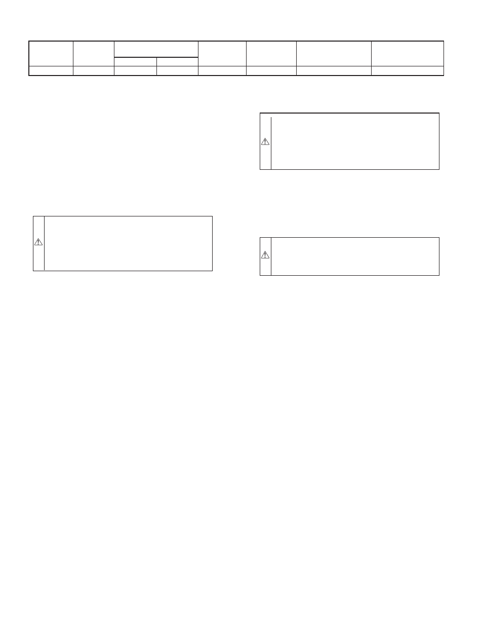
TABLE 6–ELECTRICAL DATA
UNIT SIZE
VOLTS-
HERTZ-
PHASE
OPERATING
VOLTAGE RANGE
MAXIMUM
UNIT AMPS
MINIMUM
WIRE GAGE
MAXIMUM
WIRE LENGTH (FT)‡
MAXIMUM
FUSE OR CKT BKR
AMPS†
Maximum*
Minimum*
042090
115–60–1
127
104
9.0
14
31
15
* Permissible limits of the voltage range at which the unit operates satisfactorily.
† Time-delay type is recommended.
‡ Length shown is as measured 1 way along wire path between unit and service panel for maximum 2 percent voltage drop.
—14—