Bryant 312AAV User Manual
Page 13
WARNING: The cabinet MUST have an uninterrupted
or unbroken ground according to NEC ANSI/NFPA
70-1999 and Canadian Electrical Code CSA C22.1 or
local codes to minimize personal injury if an electrical
fault should occur. This may consist of electrical wire or
conduit approved for electrical ground when installed in
accordance with existing electrical codes. Do not use gas
piping as an electrical ground. Failure to follow this
warning could result in electrical shock, fire, or death.
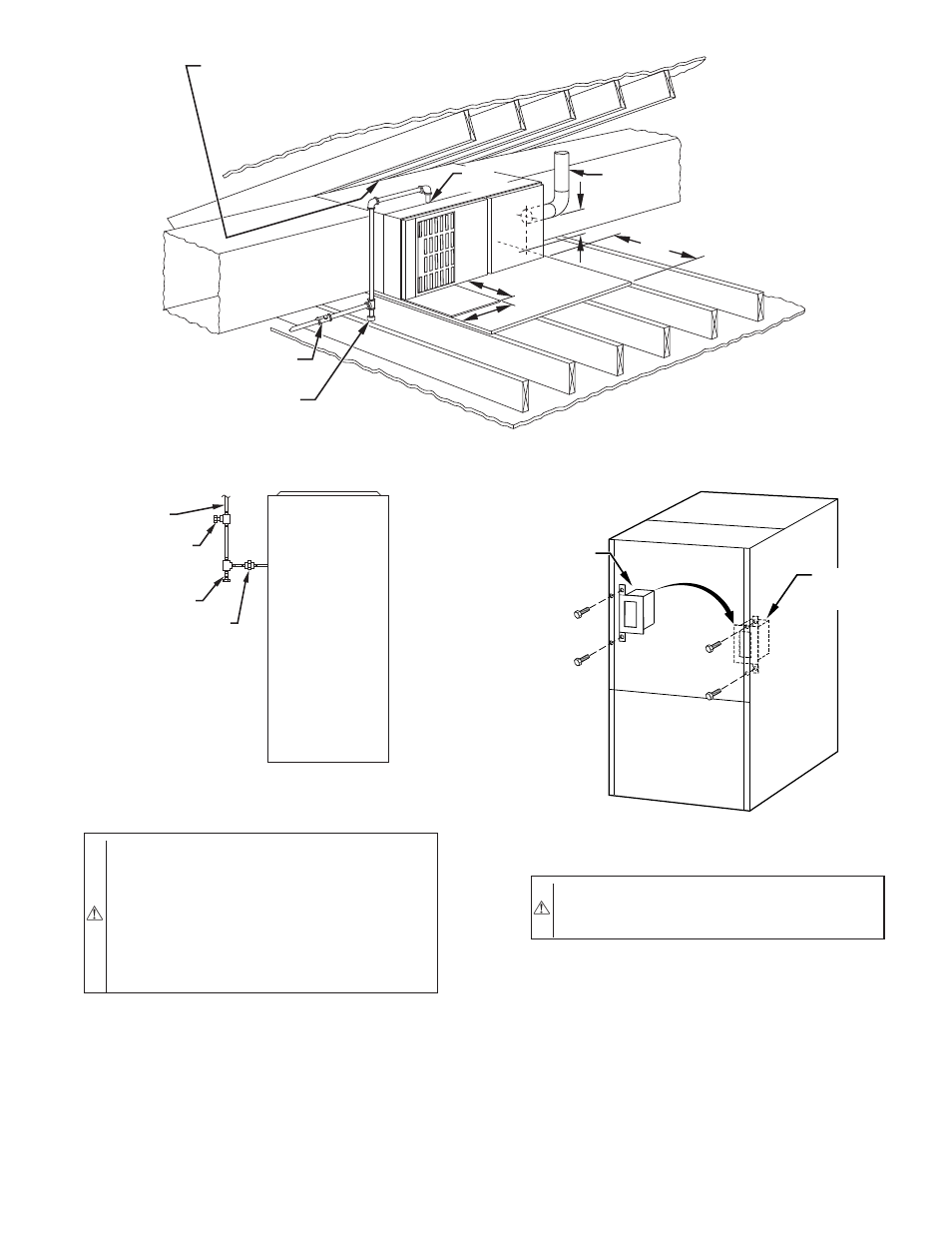
J-BOX RELOCATION
1. Remove 1 screw holding auxiliary J-box. (See Fig. 19.)
2. Cut wire tie on loop in wires to J-box.
3. Locate box to desired location.
4. Fasten J-Box to casing with screw.
5. Remove U-shaped cut-out from outer door to clear J-Box.
6. Route J-box wires within furnace away from sharp edges
and hot surfaces.
CAUTION: If manual disconnect switch is to be
mounted on furnace, select a location where a drill or
fastener will not contact electrical or gas components.
B. 24–v Wiring
Make field 24-v connections at the 24-v terminal strip. (See Fig.
22.) Connect terminal Y/Y2 as shown in Fig. 21 for proper cooling
operation. Use only AWG No. 18, color-coded, copper thermostat
wire.
The 24-v circuit contains an automotive-type, 3-amp fuse located
on the control. Any direct shorts during installation, service, or
maintenance could cause this fuse to blow. If fuse replacement is
required, use ONLY a 3-amp fuse of identical size.
C. Accessories
1. Electronic Air Cleaner (EAC)
Fig. 17–Typical Attic Installation
A00347
30-IN. MIN
WORK AREA
6″ MIN
TYPE-B
VENT
24″
24″
SHEET
METAL
SEDIMENT
TRAP
MANUAL SHUTOFF
GAS VALVE
LINE CONTACT ONLY PERMISSIBLE BETWEEN
LINES FORMED BY INTERSECTIONS OF
THE TOP AND TWO SIDES OF THE FURNACE
JACKET AND BUILDING JOISTS,
STUDS, OR FRAMING.
GAS
ENTRY
Fig. 18–Typical Gas Pipe Arrangement
A93324
UNION
SEDIMENT
TRAP
MANUAL
SHUTOFF
VALVE
(REQUIRED)
GAS
SUPPLY
Fig. 19–Relocating J-Box
A93051
ALTERNATE
FIELD
LOCATION
FACTORY
INSTALLED
LOCATION
—13—