Bryant 312AAV User Manual
Page 18
The thermostat closes the R-to-G-and-Y1 circuits for
low-cooling or closes the R-to-G-and-Y1-and-Y2 cir-
cuits for high-cooling. The R to Y1 circuit starts the
outdoor unit on low-cooling speed, and the R-to-G-
and-Y1 circuit starts the furnace blower motor BLWM
on low-cool speed (same speed as LO-HEAT). The
R-to-Y1-and-Y2 circuits start the outdoor unit on high-
cooling speed, and the R-to-G-and-Y/Y2 circuits start
the furnace blower motor BLWM on COOL speed.
The electronic air cleaner terminal EAC-1 is energized
with 115 vac whenever the blower motor BLWM is
operating.
When the thermostat is satisfied, the R-to-G-and-Y1 or
R-to-G-and-Y1-and-Y2 circuits are opened. The outdoor
unit stops, and the furnace blower BLWM and electronic
air cleaner terminal EAC-1 will remain energized for an
additional 90 seconds. Jumper Y1 to DHUM to reduce
the cooling off-delay to 5 seconds. (See Fig. 22.)
NOTE: The air conditioning relay disable jumper ACRDJ must
be disconnected to allow thermostat control of the outdoor unit
staging. (See Fig. 22.)
4. Thermidistat Mode
(See Fig. 24, 25, 26, and 27 for Thermidistat connections)
The dehumidification output, DHUM on the Thermidistat
should be connected to the furnace control thermostat
terminal DHUM. When there is a dehumidify demand, the
DHUM input is activated, which means 24 vac signal is
removed from the DHUM input terminal. In other words,
the DHUM input logic is reversed. The DHUM input is
turned ON when no dehumidify demand exists. Once 24
vac is detected by the furnace control on the DHUM input,
the furnace control operates in Thermidistat mode. If the
DHUM input is off for more than 48 hours, the furnace
control reverts back to non-Thermidistat mode.
The cooling operation described in item 3 above also
applies to operation with a Thermidistat. The exceptions are
listed below:
a. When the R-to-G-and-Y1 circuit is closed and there is a
demand for dehumidification, the furnace blower motor
BLWM will continue running at low-cool speed (same
speed as LO-HEAT).
b. When the R-to-G-and Y/Y2 circuit is closed and there is
a demand for dehumidification, the furnace blower
motor BLWM will drop the blower speed from COOL to
HI-HEAT for a maximum of 10 minutes before reverting
back to COOL speed. If there is still a demand for
dehumidification after 20 minutes, the furnace control
CPU will drop the blower speed back to HI-HEAT
speed. This alternating 10-minute cycle will continue as
long as there is a call for cooling.
c. When the
″call for cooling″ is satisfied and there is a
demand for dehumidification, the cooling blower-off
delay is decreased from 90 seconds to 5 seconds.
5. Continuous Blower Mode
When the R-to-G circuit is closed by the thermostat, the
blower motor BLWM will operate on continuous-blower
speed (can be set to LO-HEAT, HI-HEAT, or COOL
speed). Factory default is LO-HEAT speed. Terminal
EAC-1 is energized as long as the blower motor BLWM is
energized.
During a call for heat, the blower BLWM will stop during
igniter warm-up (17 seconds), ignition, and blower-ON
delay (45 seconds in low-heat, and 25 seconds in high-heat),
allowing the furnace heat exchangers to heat up more
quickly, then restarts at the end of the blower-ON delay
period at LO HEAT or HI HEAT speed.
The blower motor BLWM will revert to continuous-blower
speed after the heating cycle is completed. In high-heat, the
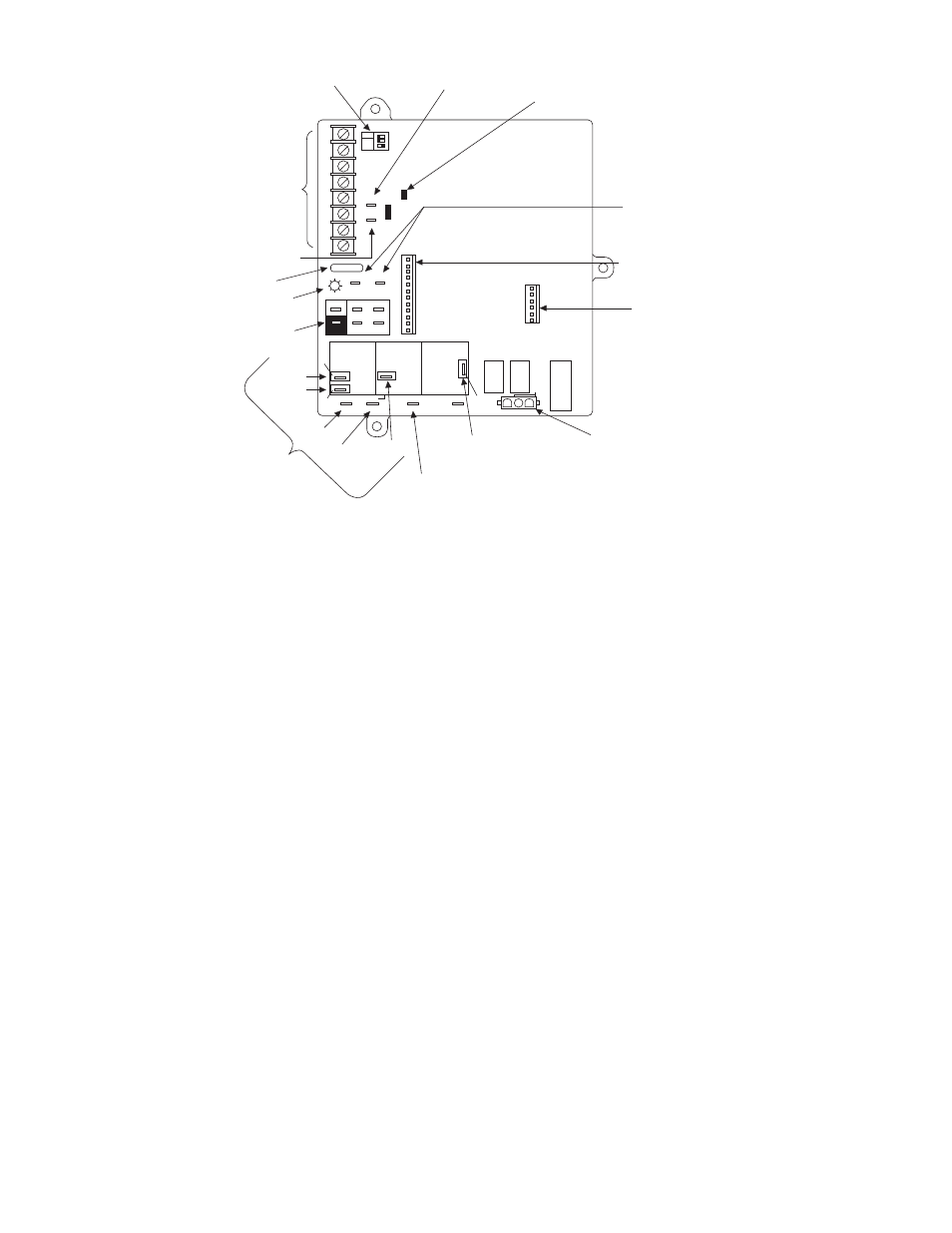
Fig. 22–Furnace Control
A00380
LHT
OFF
DLY
ON
OFF
W2
BLW
24-V-THERMOSTAT
TERMINALS
SETUP SWITCHES
LOW-HEAT ONLY AND
BLOWER OFF-DELAY
TWINNING AND/OR
COMPONENT TEST
TERMINAL
ACRDJ - AIR CONDITIONING
RELAY DISABLE JUMPER
TRANSFORMER 24-VAC
CONNECTIONS
PL1 - LOW VOLTAGE MAIN
HARNESS CONNECTOR
PL3 - ICM CONTROL
HARNESS CONNECTOR
HUMIDIFIER TERMINAL
(24-VAC 0.5 AMP MAX.)
3-AMP FUSE
LED OPERATION &
DIAGNOSTIC LIGHT
115-VAC (L2) NEUTRAL
CONNECTIONS
PL2 - HOT SURFACE
IGNITER & INDUCER
MOTOR CONNECTOR
115-VAC (L1) LINE
VOLTAGE CONNECTION
EAC-1 TERMINAL
(115-VAC 1.0 AMP MAX.)
BLOWER SPEED
SELECTION TERMINALS
HI HEAT
LO HEAT
SPARE-1
SPARE-2 COOL
Y1
DHUM
G
COM
24V
WW1
Y/Y2
R
TEST/TWIN
HUM
1 2 3
PL
T
A
CRDJ
0.5-AMP024 VAC
FUSE 3-AMP
SEC-1
SEC-2
PL1
NEUTRAL-L2
1
EAC-2
BHT/CLR
BHI/LOR
PL3 1
BLWR
COOL
SPARE-1
SPARE-2
1-AMP@115 VAC
EAC-1
PR-1
IDR
HSIR
IDM
IHI/LOR
PL2
1
HSI HI LO
STATU
S
COD
EL
E
D
HI HEA
T
LO HEA
T
L1
—18—