Bryant 312AAV User Manual
Page 2
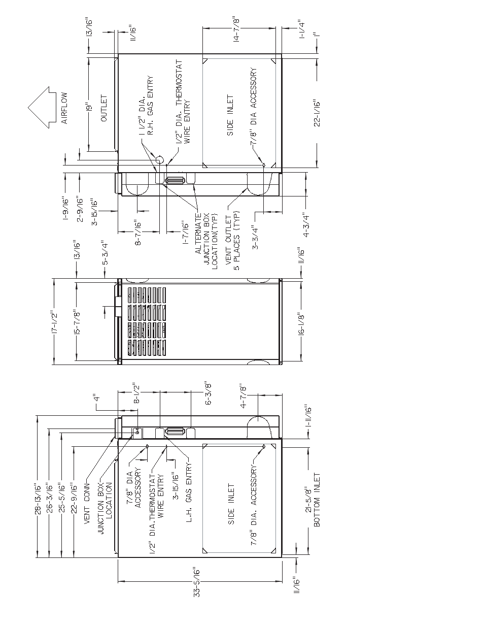
Fig.
1–Dimensional
Drawing
A00264
(Optional)
(Optional)
(Optional)
*
NO
TES:
1.
Tw
o additional
7 /8
-in.
dia holes are located in the top plate
.
2.
Minim
um retur
n-air openings at fur
nace
, based on metal duct.
If fle
x duct is used,
see fle
x duct man
uf
acturer’
s recommendations f
or equiv
alent diameters
.
3.
Minim
um retur
n-air opening at fur
nace:
a.
F
or 800 CFM–16-in.
round or 14
1 /2
x 12-in.
rectangle
.
b.
F
or 1200 CFM–20-in.
round or 14
1 /2
x 19
1 /2
-in.
rectangle
.
* In upflo
w
, one optional v
ent is located on the bottom of the outer door
.
—2—
See also other documents in the category Bryant Kiln:
- Multipoise Condensing Gas 915S (16 pages)
- CONDENSING GAS FURNACE 340MAV (12 pages)
- Deluxe 4-Way Multipoise Variable-Capacity Direct-Vent Condensing Gas Furnace A93040 (16 pages)
- 311AAV (8 pages)
- 373LAV (20 pages)
- 4-Way Multipoise Fixed-Capacity Direct-Vent Condensing Gas 340MAV (44 pages)
- SERIES E 348 (8 pages)
- CK5B (8 pages)
- Bruant 4 Way Gas 355AAV (60 pages)
- GAS-FIRED INDUCED-COMBUSTION FURNACES 383KAV (16 pages)
- CK3B (8 pages)
- gas furnaces (24 pages)
- PLUS 95S 355CAV (14 pages)
- 355MAV (20 pages)
- Gas Furance 315AAV (60 pages)
- 331JAV (12 pages)
- 352MAV (12 pages)
- 352MAV (16 pages)
- 350MAV (44 pages)
- 359AAV (22 pages)
- 355CAV (62 pages)
- A10252 (10 pages)
- 367AAN (8 pages)
- HIGH EFFICIENCY GAS FURNACE 359AAV (8 pages)
- Multipurpose Oil 369AAN (12 pages)
- 369AAN (8 pages)
- SERIES A 355CAV (62 pages)
- 398AAZ (2 pages)
- 376B (8 pages)
- 345MAV (44 pages)
- 345MAV (40 pages)
- GAS-FIRED INDUCED-COMBUSTION FURNACE 393AAV (12 pages)
- 313AAV/JAV (12 pages)
- 310 (8 pages)
- PLUS 90X 353AAV (22 pages)
- 395CAV (20 pages)
- 395CAV (12 pages)
- Gas Fired Forced Air 394 (6 pages)
- Oil 374RAN (8 pages)
- 396HAD (8 pages)
- 394HAD (8 pages)
- 4-WAY MULTIPOISE FIXED-CAPACITY CONDENSING GAS FURNACE 345MAV (16 pages)
- 331AAV (12 pages)
- SERIES E A10252 (12 pages)