Bryant 312AAV User Manual
Page 27
Place LHT in ON position. Jumper R to W/W1 and W2 to
check high-gas-heat temperature rise. To check low-gas-
heat temperature rise, remove jumper to W2. Determine air
temperature rise for both high and low fire. Do not exceed
temperature rise ranges specified on unit rating plate for
high-and low-fire.
The furnace must operate within the temperature rise ranges
specified on the furnace rating plate. Determine the air
temperature as follows:
a. Place thermometers in return and supply ducts as close to
furnace as possible. Be sure thermometers do not see
heat exchangers so that radiant heat does not affect
readings. This practice is particularly important with
straight-run ducts.
b. When thermometer readings stabilize, subtract return-air
temperature from supply-air temperature to determine
air temperature rise.
NOTE: If the temperature rise is outside this range, first check:
(1.) Gas input for low-and high-fire opeation.
(2.) Derate for altitude if applicable.
(3.) Return and supply ducts for excessive restrictions
causing static pressures greater than 0.50–in. wc.
c. Adjust air temperature rise by adjusting blower speed.
Increase blower speed to reduce temperature rise. De-
crease blower speed to increase temperature rise. Fro
high fire, speed selection can be med-high, med
(5–speed blowers only), or med-low (factory setting).
For low fire, speed selection can be low (factory setting),
med-low, or med (5–speed blowers only).
WARNING: Disconnect 115-v electrical power before
changing speed tap. Failure to follow this warning could
result in personal injury.
d. To change motor speed selection for high heat, remove
blower motor lead from control HI-HEAT terminal. (See
Fig. 22 and 23.) Select desired blower motor speed lead
from 1 of the other terminals and relocate it to the
HI-HEAT terminal. (See Table 11 for lead color identi-
fication). Reconnect original lead to SPARE terminal.
Follow this procedure for proper selection of COOL and
LO-HEAT speed selection.
CAUTION: Recheck temperature rise. It must be within
limits specified on the rating plate. Recommended opera-
tion is at the midpoint of rise range or above.
8. Set thermostat heat anticipator.
a. When using a nonelectric thermostat, the thermostat
heat-anticipation must be set to match the amp draw of
the electrical components in the R-W/W1 circuit. Accu-
rate amp draw readings can be obtained at the wires
normally connected to thermostat subbase terminals, R
and W/W1.
Fig. 16 illustrates an easy method of obtaining actual
amp draw. The amp reading should be taken after blower
motot has started and furnace is operating in low-heat.
To operate furnace in low-heat, first move LHT to ON
position, then connect ammeter wires as shown in Fig.
37. The thermostat anticipator should NOT be in th
circuit while measuring current. If thermostat has no
subbase, the thermostat must be disconnected from R
and W/W1 wires during current measurement. Return
LHT to OFF after completing the reading. See thermo-
stat manufacturer’s instructions for adjusting heat-
anticipator.
b. When using an elctronic thermostat, set cycle rate for 3
cycles per hr.
V. CHECK SAFETY CONTROLS
The flame sensor, gas valve, and pressure switch were all checked
in the Start-up procedure section as part of normal operation.
1. Check Main Limit Switches
This control shuts off combustion control system and energizes
air-circulating blower motor, if furnace overheats.
Recommended method of checking this limit control is to gradu-
ally block off return air after furnace has been operating for a
period of at least 5 minutes. As soon as limit control has shut off
burners, return-air opening should be unblocked to permit normal
air circulation. By using this method to check limit control, it can
be established that limit is functioning properly and will operate if
there is a restricted return-air supply or motor failure. If limit
control does not function during this test, cause must be deter-
mined and corrected.
TABLE 11–SPEED SELECTION
COLOR
SPEED
AS SHIPPED
White
Common
BLW
Black
High
COOL
Yellow
Med-High
SPARE
Orange†
Med
SPARE
Blue
Med-Low
HI-HEAT
Red
Low*
LO HEAT
* Continuous-blower speed-as shipped default
† Available on 5–speed blowers only.
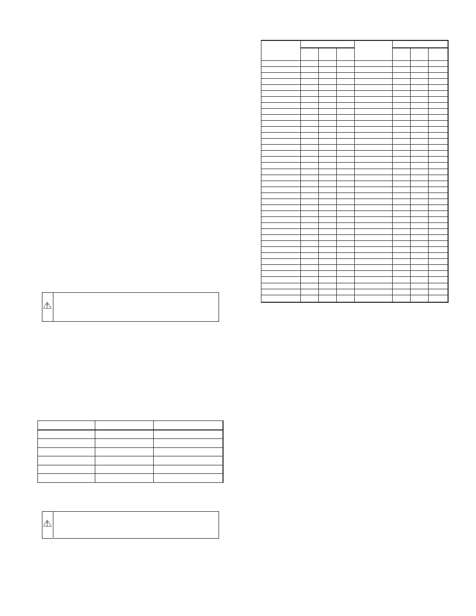
TABLE 12–GAS RATE (CU FT/HR)
SECONDS
FOR 1
REVOLUTION
SIZE OF TEST DIAL
SECONDS
FOR 1
REVOLUTION
SIZE OF TEST DIAL
1
Cu Ft
2
Cu Ft
5
Cu Ft
1
Cu Ft
2
Cu Ft
5
Cu Ft
10
360
720
1800
50
72
144
360
11
327
655
1636
51
71
141
355
12
300
600
1500
52
69
138
346
13
277
555
1385
53
68
136
340
14
257
514
1286
54
67
133
333
15
240
480
1200
55
65
131
327
16
225
450
1125
56
64
129
321
17
212
424
1059
57
63
126
316
18
200
400
1000
58
62
124
310
19
189
379
947
59
61
122
305
20
180
360
900
60
60
120
300
21
171
343
857
62
58
116
290
22
164
327
818
64
56
112
281
23
157
313
783
66
54
109
273
24
150
300
750
68
53
106
265
25
144
288
720
70
51
103
257
26
138
277
692
72
50
100
250
27
133
267
667
74
48
97
243
28
129
257
643
76
47
95
237
29
124
248
621
78
46
92
231
30
120
240
600
80
45
90
225
31
116
232
581
82
44
88
220
32
113
225
563
84
43
86
214
33
109
218
545
86
42
84
209
34
106
212
529
88
41
82
205
35
103
206
514
90
40
80
200
36
100
200
500
92
39
78
196
37
97
195
486
94
38
76
192
38
95
189
474
96
38
75
188
39
92
185
462
98
37
74
184
40
90
180
450
100
36
72
180
41
88
176
439
102
35
71
178
42
86
172
429
104
35
69
173
43
84
167
419
106
34
68
170
44
82
164
409
108
33
67
167
45
80
160
400
110
33
65
164
46
78
157
391
112
32
64
161
47
76
153
383
116
31
62
155
48
75
150
375
120
30
60
150
49
73
147
367
—27—