Bryant 312AAV User Manual
Page 8
DOWNFLOW FURNACES
Connect supply-air duct to supply-air opening on furnace. The
supply-air duct attachment must ONLY be connected to furnace
supply/outlet or air conditioning coil casing (when used). When
installed on combustible material, supply-air duct attachment must
ONLY be connected to an accessory subbase or factory approved
air conditioning coil casing. DO NOT cut main furnace casing to
attach supply side air duct, humidifier, or other accessories. All
accessories MUST be connected external to furnace casing. Supply
air opening duct flanges must be modified per Fig. 14.
HORIZONTAL FURNACES
Connect supply-air duct to supply air opening on furnace. The
supply-air duct attachment must ONLY be connected to furnace
supply/outlet or air conditioning coil casing (when used). DO NOT
cut main furnace casing to attach supply side air duct, humidifier,
or other accessories. All accessories MUST be connected external
to furnace casing. Supply air opening duct flanges must be
modified per Fig. 14.
D. Return Air Connections
DOWNFLOW AND HORIZONTAL FURNACES
WARNING: Never connect return-air ducts to the back
of the furnace. A failure to follow this warning can cause
a fire, personal injury, or death.
The return-air duct must be connected to return-air opening
(bottom inlet) as shown in Fig. 1. DO NOT cut into casing sides
(left or right). Side opening is permitted for only upflow furnaces.
Bypass humidifier connections should be made at ductwork or coil
casing sides exterior to furnace.
UPFLOW FURNACES
The return-air duct must be connected to bottom, sides (left or
right), or a combination of bottom and side(s) of main furnace
casing as shown in Fig. 1. Bypass humidifier may be attached into
unused side return air portion of the furnace casing.
INSTALLATION
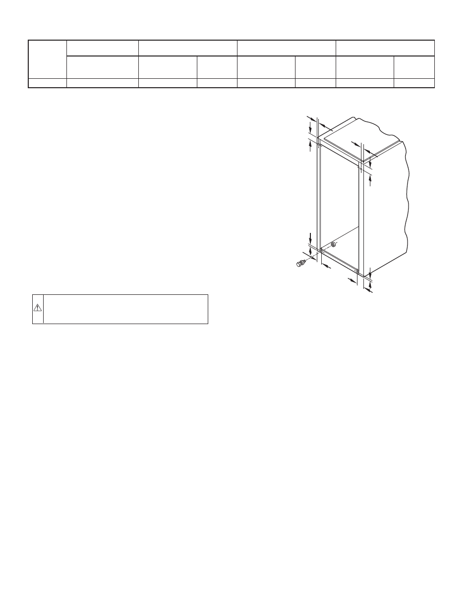
I. LEVELING LEGS (IF DESIRED)
When furnace is used in upflow position with side inlet(s), leveling
legs may be desired. (See Fig. 9.) Install field-supplied, corrosion-
resistant 5/16-in. machine bolts and nuts.
NOTE: The maximum length of bolt should not exceed 1-1/2 in.
1. Position furnace on its back. Locate and drill a 5/16-in.
diameter hole in each bottom corner of furnace. (See Fig.
9.) Holes in bottom closure panel may be used as guide
locations.
2. For each hole, install nut on bolt and then install bolt and
nut in hole. (Install flat washer if desired.)
3. Install another nut on other side of furnace base. (Install flat
washer if desired.)
4. Adjust outside nut to provide desired height, and tighten
inside nut to secure arrangement.
NOTE: Bottom closure must be used when leveling legs are used.
NOTE: Remove and discard bottom closure panel when bottom
inlet is used.
II. BOTTOM CLOSURE PANEL
These furnaces are shipped with bottom closure panel installed in
bottom return-air opening. This panel MUST be in place when side
return air is used.
To remove bottom closure panel, perform the following:
1. Tilt or raise furnace and remove 2 screws holding front
filler panel. See Fig. 10)
2. Rotate front filler panel downward to release holding tabs.
3. Remove bottom closure panel.
4. Reinstall front filler panel and screws.
NOTE: Side return-air openings can ONLY be used in UPFLOW
configurations.
III. DOWNFLOW INSTALLATION
NOTE: For downflow applications, this furnace is approved for
use on combustible flooring when special base (Part No.
KGASB0201ALL) is used. Special base is not required when this
furnace is installed on manufacturer’s Coil Assembly Part No.
CD5 or CK5, or Coil Box Part No. KCAKC is used.
1. Determine application being installed from Table 3.
2. Construct hole in floor per dimensions specified in Table 3
and Fig. 11.
3. Construct plenum to dimensions specified in Table 3 and
Fig. 11.
4. If downflow subbase (KGASB) is used, install as shown in
Fig. 12.
TABLE 2–MINIMUM FREE AREA OF COMBUSTION AIR OPENING*
312AAV
FURNACE
INPUT
(BTUH)
AIR FROM INDOOR
UNCONFINED SPACE
OUTDOOR AIR THROUGH
VERTICAL DUCTS
OUTDOOR AIR THROUGH
HORIZONTAL DUCTS
OUTDOOR AIR THROUGH
SINGLE DUCT
Free Area
of Opening
(Sq In.)
Free Area of
Opening and Duct
(Sq. In.)
Round Pipe
(in. Dia)
Free Area of
Opening and Duct
(sq In.)
Round Pipe
(in. Dia)
Free Area of
Opening and Duct
(Sq In.)
Round Pipe
(In. Dia)
88,000
100
22.0
6
44.0
8
29.33
7
* Free area shall be equal to or greater than the sum of the areas of all vent connectors in the confined space. Opening area must be increased if other gas appliances in
the space require combustion air.
Fig. 9–Leveling Legs
A89014
1
3
/
4
″
1
3
/
4
″
1
3/
4
″
1
3/
4
″
5/
16
″
5
/
16
″
5/
16
″
5/
16
″
(44mm)
(8mm)
(44mm)
(8mm)
(8mm)
(8mm)
(44mm)
(44mm)
—8—