Bryant 312AAV User Manual
Page 26
d. Check and verify orifice size in furnace. NEVER AS-
SUME THE ORIFICE SIZE. ALWAYS CHECK AND
VERIFY.
e. Turn off all other gas appliances and pilots.
f. Move setup switch LHT to ON position. (See Fig. 22.)
This keeps furnace locked in low-heat operation.
g. Jumper R to W/W1.
h. Let furnace run for 3 minutes in low-heat operation.
i. Measure time (in sec) for gas meter to complete 1
revolution. Note reading.
j. Refer to Table 11 for cubic ft of gas per hr.
k. Multiply gas rtate cu ft/hr by heating value (Btu/cu ft).
l. Move setup switch LHT to OFF position and jumper R
and W2 thermostat connections. (See Fig. 22.) This keeps
furnace locked in high-heat operation. Repeat items h
through k for high-heat operation.
EXAMPLE: (High–heat operation at 0-2000 ft altitude)
Furnace input from rating plate is 88,000 Btuh.
Btu heating input = Btu/cu ft X cu ft/hr
Heating value of gas = 1050 Btu/cu ft
Time for 1 revolution of 2-cu ft dial = 87 sec
Gas rate = 83 cu ft/hr (from Table 11)
Btu heating input = 83 X 1050 = 87,150 Btuh. In this
example, the orifice size and manifold pressure adjustment
is within ±2 percent of the furnace input rate.
NOTE: Measured gas inputs (high-heat and low-heat) must be
within ± 2 percent of that stated on furnace rating plate when
installed at sea level or derated per that stated above when installed
at higher altitudes.
m. Remove jumper across R, W/W1, and W2 thermostat
connections to terminate call for heat.
7. Set temperature rise.
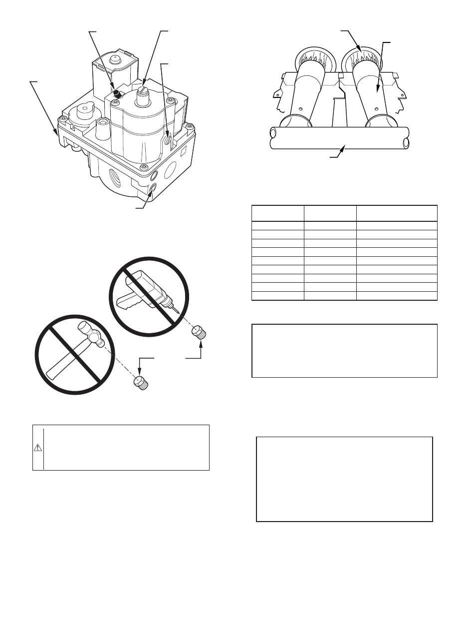
Fig. 32–Redundant Automatic Gas Control Valve
A00158
ON/OFF
SWITCH
INLET
PRESSURE
TAP
ON
O
F
F
MANIFOLD
PRESSURE
TAP
LOW-FIRE
ADJUSTMENT
ALLEN SCREW
(UNDER CAP)
HIGH-FIRE
ADJUSTMENT
ALLEN SCREW
(UNDER CAP)
Fig. 33–Orifice Hole
A93059
BURNER
ORIFICE
CAUTION: DO NOT redrill orifices. Improper drilling
(burrs, out-of-round holes, etc.) can cause excessive
burner noise and misdirection of burner flames. This can
result in flame impingement of heat exchangers, causing
failures.
Fig. 34-Burner Flame
A89020
;;
;;
BURNER FLAME
BURNER
MANIFOLD
TABLE 10–ALTITUDE DERATE MULTIPLIER FOR U.S.A.
ALTITUDE
(FT)
PERCENT
OF DERATE
DERATE MULTIPLIER
FACTOR FOR U.S.A.*
0–2000
0
1.00
2001–3000
8–12
0.90
3001–4000
12–16
0.86
4001–5000
16–20
0.82
5001–6000
20–24
0.78
6001–7000
24–28
0.74
7001–8000
28–32
0.70
8001–9000
32–36
0.66
9001–10,000
36–40
0.62
* Derate multiplier factor is based on midpoint altitude for altitude range.
EXAMPLE:
88,000 BTUH INPUT FURNACE INSTALLED AT 4300 FT.
Derate
Furnace Input Rate
Furnace Input Rate
X
Multiplier
=
at Installation
at Sea Level
Factor
Altitude
88,000
X
0.82
=
72,160
—26—