Understanding the arn module locations, Understanding the arn module locations -9, Figure 1-4 – Bay Technical Associates BayStack ARN Routers none User Manual
Page 39: Arn module locations -9, Installing the baystack advanced remote node, Figure 1-4. arn module locations
Installing the BayStack Advanced Remote Node
114200 Rev. A
1-9
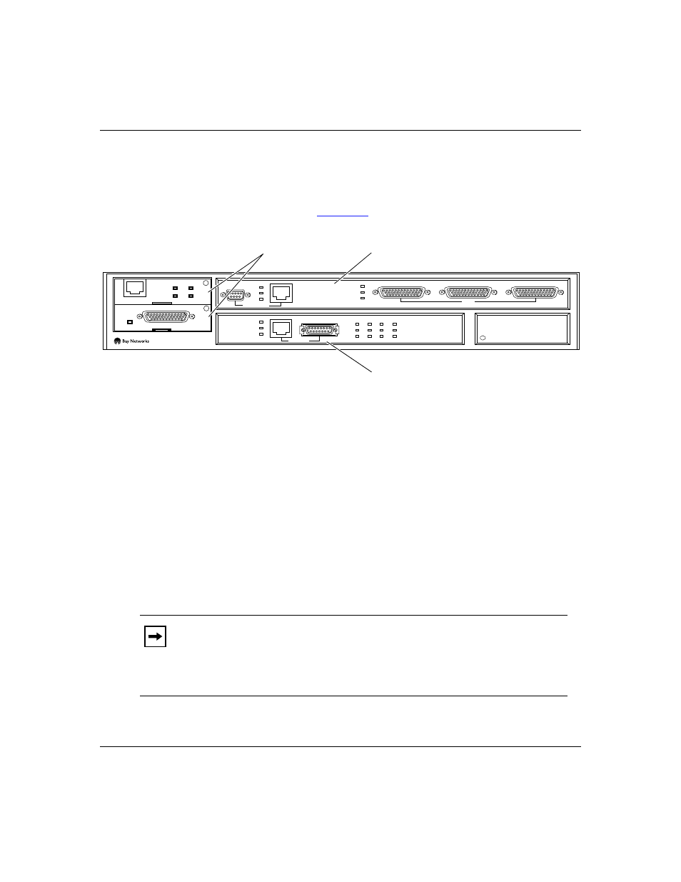
Understanding the ARN Module Locations
The ARN is designed to scale to your needs. In addition to either an Ethernet or
token ring base module, the ARN can contain an optional expansion module and
up to two adapter modules (
).
Figure 1-4.
ARN Module Locations
The ARN is available in the following base module configurations:
•
One Ethernet AUI and Ethernet 10Base-T interface
•
One Token Ring interface (STP only)
The ARN supports the following expansion modules:
•
One Ethernet AUI and Ethernet 10Base-T interface
•
One Token Ring interface (STP and UTP)
•
Three serial interfaces
•
One Ethernet AUI and Ethernet 10Base-T interface and three serial interfaces
•
One Token Ring interface (STP and UTP) and three serial interfaces
Note:
The Ethernet base and expansion modules can also contain an optional
data collection module (DCM). The DCM gathers Ethernet statistics for a
remote monitoring (RMON) utility. Your network administrator can refer to
Configuring Remote Access for additional information about how to enable
and use the DCM.
ARN0006A
STP
Adapter modules
Expansion module
Base module
COM3
COM4
COM5
COM
U
D
DD
B1
B2
RLSD
Run
Boot
Fail
Pwr
RPS
Fan
Base
Adapter1
Adapter2
Expansion
DCM
PCMCIA
BayStack
Advanced Remote Node
RLSD3
RLSD4
RLSD5
1
2
Serial
Serial
ISDN BRI
withNT1
RCVR
NSRT
WFLT
Tx
Rx
Cl
10BaseT
AUI
Ethernet 1
Token Ring 2
UTP