Ethernet attachment unit interface (aui), Table c-3 – Bay Technical Associates BayStack ARN Routers none User Manual
Page 125
Technical Specifications
114200 Rev. A
C-5
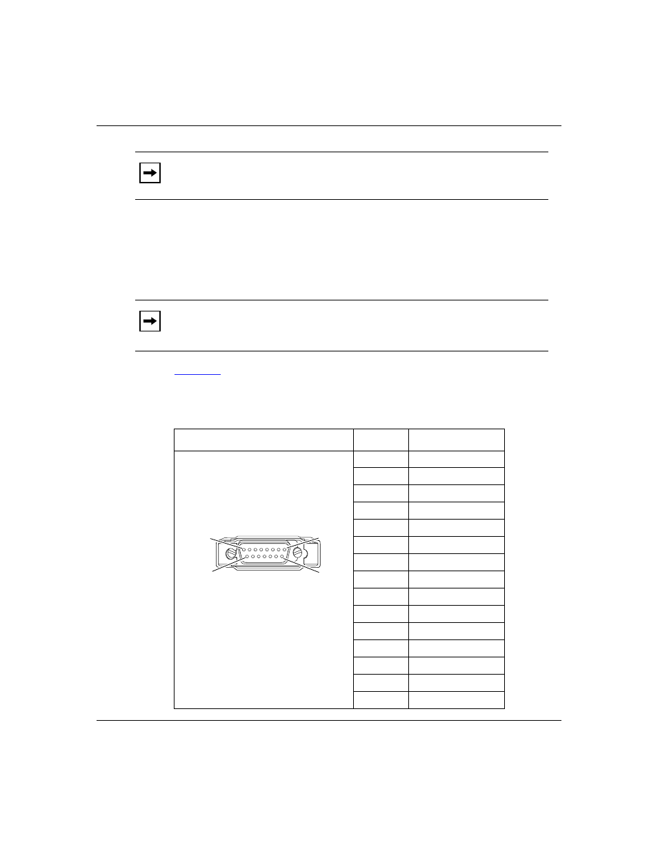
Ethernet Attachment Unit Interface (AUI)
The ARN Ethernet base module, Ethernet expansion module, and
Ethernet/tri-serial expansion modules contain a 10Base-T standard 802.3 AUI
DB-15 receptacle with a slide lock.
shows the pin assignments for the standard 15-pin AUI receptacle on
the ARN base or expansion module and identifies its pin locations.
Note:
Refer to the Cable Guide for Routers and BNX Platforms for the proper
cables or cable pinouts to use for each interface type.
Note:
The AUI is designed only for connection to a transceiver. Connecting
the AUI directly to an AUI on an Ethernet station (without a transceiver)
violates IEEE 802.3 standards.
Table C-3.
AUI Pin Assignments
Pin Assignment
Pin No.
Signal Name
1
GND
2
CI-A
3
DO-A
4
GND
5
DI-A
6
+12 V dc Return
7
Not used
8
Not used
9
CI-B
10
DO-B
11
GND
12
DI-B
13
+12 V dc
14
GND
15
GND
Pin 1
Pin 8
Pin 9
Pin 15