Figure b-1, Table b-1, Installing and operating baystack arn routers b-2 – Bay Technical Associates BayStack ARN Routers none User Manual
Page 104: Figure b-1. arn module locations, Table b-1. quick-start connector names and numbers
Installing and Operating BayStack ARN Routers
B-2
114200 Rev. A
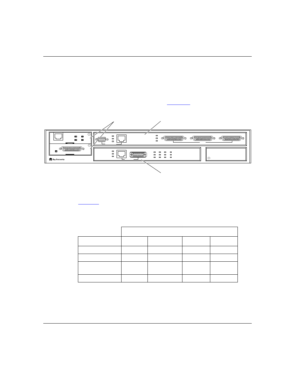
Understanding Quick-Start Connector Names and Numbers
The Quick-Start script assigns a name and number to each interface, depending on
its location on the ARN.
In addition to either an Ethernet or token ring base module, the ARN can contain
expansion modules and adapter modules (
Figure B-1.
ARN Module Locations
provides the connector names and numbers you should use during the
Quick-Start procedure.
*. The Quick-Start script does not support initial ISDN or V.34 interface configuration.
Table B-1.
Quick-Start Connector Names and Numbers
Module
Interface*
Base
Expansion
Adapter 1
Adapter 2
Ethernet
XCVR1
XCVR2
N/A
N/A
Token Ring
MAU1
MAU2
N/A
N/A
Serial
N/A
COM3, COM4,
or COM5
COM1
COM2
56/64K DSU/CSU
N/A
N/A
COM1
COM2
ARN0006A
STP
Adapter modules
Expansion module
Base module
COM3
COM4
COM5
COM
U
D
DD
B1
B2
RLSD
Run
Boot
Fail
Pwr
RPS
Fan
Base
Adapter1
Adapter2
Expansion
DCM
PCMCIA
BayStack
Advanced Remote Node
RLSD3
RLSD4
RLSD5
1
2
Serial
Serial
ISDN BRI
withNT1
RCVR
NSRT
WFLT
Tx
Rx
Cl
10BaseT
AUI
Ethernet 1
Token Ring 2
UTP