Brother 1270N User Manual
Page 91
CHAPTER 4 DISASSEMBLY AND RE-ASSEMBLY
4-21
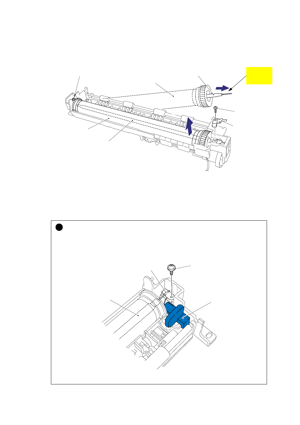
(12) Remove the one M3x10 Taptite screw securing the halogen lamp connector plate at the
drive unit side of the fixing unit frame and then loosen the M3x6 screw at the other side.
(13) Lift the right hand end of the heat roller and remove the halogen heater lamp from the heat
roller.
Fig. 4-37
NOTE:
When re-assembling the halogen heater lamp, ensure that the direction of the halogen heater
lamp is correct referring to the figure above.
!
CAUTION:
•
Never touch the surface of the halogen heater lamp.
•
When securing the screw to assemble the halogen lamp connector plate, ensure you use
the plastic jig as shown in the figure below to avoid damaging the edge of the halogen
heater lamp.
Fig. 4-38
Halogen heater lamp
Heat roller
Taptite, pan M3x10
Screw, cup M3x6
Halogen heater lamp
Heat roller
Colored side
115V: Yellow
230V: Purple
Halogen lamp
connector plate
Taptite, pan M3x10
Halogen lamp
connector plate
Plastic jig
Halogen heater lamp
- HL-2240 (522 pages)
- HL-2240 (21 pages)
- HL-2240 (150 pages)
- HL-2240 (2 pages)
- HL 5370DW (172 pages)
- HL-2170W (138 pages)
- HL 5370DW (203 pages)
- HL 2270DW (47 pages)
- HL 2270DW (35 pages)
- HL 5370DW (55 pages)
- HL-2170W (52 pages)
- HL-2170W (137 pages)
- PT-1290 (1 page)
- DCP-383C (7 pages)
- DCP-385C (122 pages)
- MFC 6890CDW (256 pages)
- DCP-585CW (132 pages)
- DCP-385C (2 pages)
- Pocket Jet6 PJ-622 (48 pages)
- Pocket Jet6 PJ-622 (32 pages)
- Pocket Jet6 PJ-622 (11 pages)
- Pocket Jet6Plus PJ-623 (76 pages)
- PT-2700 (90 pages)
- PT-2700 (180 pages)
- PT-2100 (58 pages)
- PT-2700 (34 pages)
- PT-2700 (62 pages)
- HL 5450DN (168 pages)
- HL 5450DN (2 pages)
- HL 5450DN (2 pages)
- DCP-8110DN (22 pages)
- HL 5470DW (30 pages)
- MFC-J835DW (13 pages)
- DCP-8110DN (36 pages)
- HL 5470DW (177 pages)
- HL 5450DN (120 pages)
- DCP-8110DN (13 pages)
- HL 5470DW (34 pages)
- HL-S7000DN (9 pages)
- HL-6050D (179 pages)
- HL-6050D (37 pages)
- HL-7050N (17 pages)
- HL-6050DN (138 pages)
- PT-1280 (1 page)
- PT-9800PCN (104 pages)