Brother 1270N User Manual
Page 90
CHAPTER 4 DISASSEMBLY AND RE-ASSEMBLY
4-20
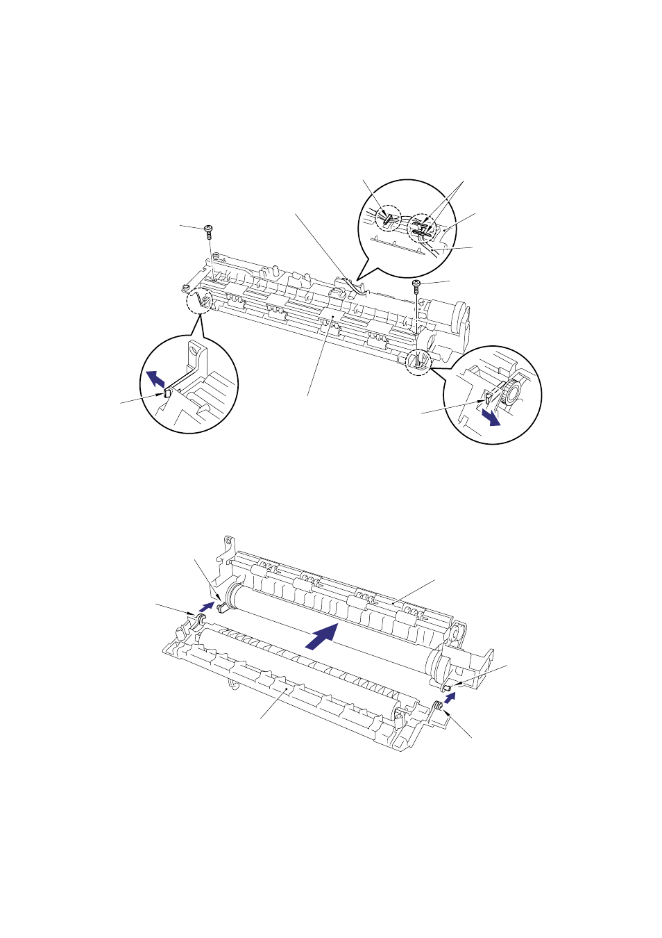
(8) Remove the two M3x20 Taptite screws from the top of the fixing unit frame.
(9) Release the thermistor harness from the hooks.
(10) Release the two hooks at the right and left sides securing the fixing unit cover to the fixing
unit frame.
Fig. 4-35
(11) Remove the fixing unit cover from the fixing unit frame.
Fig. 4-36
Fixing unit frame
Fixing unit cover
(hook)
(hook)
(hook)
(hook)
Fixing unit frame
(hook)
Thermistor harness
(hook)
Taptite, cup M3x20
Thermistor harness
Taptite, cup M3x20
Fixing unit frame
(hook)
(hook)
See also other documents in the category Brother Printers:
- HL-2240 (522 pages)
- HL-2240 (21 pages)
- HL-2240 (150 pages)
- HL-2240 (2 pages)
- HL 5370DW (172 pages)
- HL-2170W (138 pages)
- HL 5370DW (203 pages)
- HL 2270DW (35 pages)
- HL 2270DW (47 pages)
- HL 5370DW (55 pages)
- HL-2170W (137 pages)
- HL-2170W (52 pages)
- PT-1290 (1 page)
- DCP-383C (7 pages)
- DCP-385C (122 pages)
- MFC 6890CDW (256 pages)
- DCP-585CW (132 pages)
- DCP-385C (2 pages)
- Pocket Jet6 PJ-622 (48 pages)
- Pocket Jet6 PJ-622 (32 pages)
- Pocket Jet6 PJ-622 (11 pages)
- Pocket Jet6Plus PJ-623 (76 pages)
- PT-2700 (180 pages)
- PT-2100 (58 pages)
- PT-2700 (34 pages)
- PT-2700 (62 pages)
- PT-2700 (90 pages)
- HL 5450DN (2 pages)
- HL 5450DN (2 pages)
- DCP-8110DN (22 pages)
- HL 5450DN (168 pages)
- MFC-J835DW (13 pages)
- DCP-8110DN (36 pages)
- HL 5470DW (177 pages)
- HL 5450DN (120 pages)
- DCP-8110DN (13 pages)
- HL 5470DW (34 pages)
- HL-S7000DN (9 pages)
- HL 5470DW (30 pages)
- HL-6050D (179 pages)
- HL-6050D (37 pages)
- HL-7050N (17 pages)
- HL-6050DN (138 pages)
- PT-1280 (1 page)
- PT-9800PCN (75 pages)