Software mode, 1 quick start guide, Figure 1.software mode quick start guide – Cirrus Logic CDB8422 User Manual
Page 6: Section 2
6
DS692DB2
CDB8422
2. SOFTWARE MODE
Connecting a USB port cable from a PC to the USB connector (J37) on the CDB8422 and launching the provided
graphical user interface (Cirrus Logic FlexGUI) software enables one to use the board in software mode. The GUI
for the CDB8422 allows the user to configure the CS8422 and FPGA registers via the on-board I²C or SPI control
bus.
2.1
Quick Start Guide
below is a simplified quick start up guide made for user convenience. The user may choose from
steps 8 through 13 depending on the desired measurement. Refer to
for details on how the var-
ious components on the board interface with each other in different board configurations. Refer to
for descriptions on control settings in the Cirrus FlexGUI software.
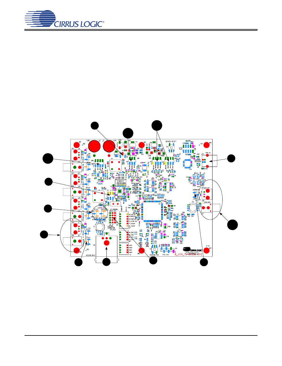
Figure 1. Software Mode Quick Start Guide
Shunt right 2 pins of J20
to receive power from
USB +5 V DC power.
Connect USB to board.
Open Flex GUI software
on PC and load quick
setup script.
*See section 2.2 for
quick setup descriptions.
Provide S/PDIF
input to board via
J1 or J7.
PCM digital audio
input can be provided
to the board via
header J22.
1
7
8
PCM digital audio output can be
received from the board via
headers J24 and J25.
Shunt top 2 pins on J4
if using optical input
J1. Shunt bottom 2
pins on J4 if using
coaxial input J7.
4
Shunt the right 2 pins on all rows.
Connect a ribbon cable to left 2
pins of all rows if external system
connect is required.
5
Shunt the middle
2 pins on J23.
2
Receive S/PDIF
output from board
via J28 or J27.
Shunt the top 2 pins
on J31.
6
AES3/EBU input
can also be
provided to the
board via J19.
9
Shunt the top 2 pins on
J21 and J29.
3
TDM input can be
provided to the board via
header J30.
10
11
12
13