System connections, Table 6. system connections, Section 4 – Cirrus Logic CDB8422 User Manual
Page 28
28
DS692DB2
CDB8422
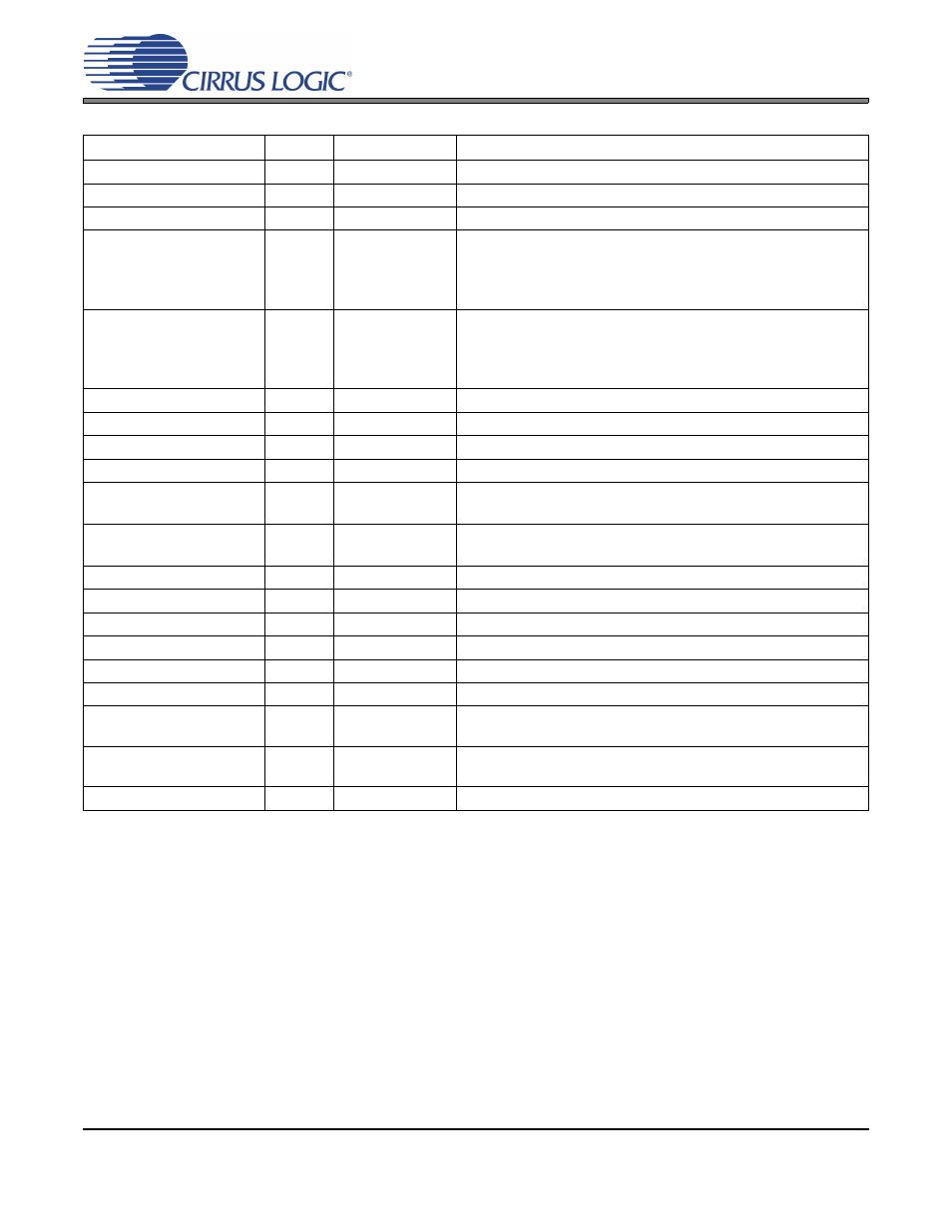
4. SYSTEM CONNECTIONS
CONNECTOR
REF
INPUT/OUTPUT
SIGNAL PRESENT
+5V
J2
Input
+5 V Power Supply
GND
J3
Input
Ground Reference
USB I/O
J37
Input/Output
USB connection to PC for I²C or SPI control port signals
RX0
RX1
RX2
RX3
J1
J5
J10
J15
Input
Input
Input
Input
CS8422 digital audio input via optical cable
RX0
RX1
RX2
RX3
J7
J6
J12
J16
Input
Input
Input
Input
CS8422 digital audio input via coaxial cable
AES/EBU INPUT
J19
Input
CS8422 digital audio input via XLR cable
OPTICAL OUT
J28
Output
CS8406 digital audio output via optical cable
COAX OUT
J27
Output
CS8406 digital audio output via coaxial cable
Input Serial Port Header
J22
Input/Output
I/O for Clocks & Data to/from the CS8422’s input serial port
Output Serial Port 1
Header
J24
Input/Output
I/O for Clocks & Data to/from the CS8422’s output serial port 1
Output Serial Port 2
Header
J25
Input/Output
I/O for Clocks & Data to/from the CS8422’s output serial port 2
TDM Input Header
J30
Input/Output
I/O for Clocks & Data to/from the CS8422’s TDM input
SPI/I2C
J26
Input/Output
I/O for external I²C or SPI control port signals
C2
J36
Input/Output
I/O for programming the micro controller (U46)
FPGA JTAG
J69
Input/Output
I/O for programming the FPGA (U58)
BOARD RESET
S5
Input
Reset for the CDB8422
FPGA PROGRAM
S1
Input
Reload Xilinx program into the FPGA from Flash (U57)
MS SEL
S3
Input
Selects master/slave mode and clock ratio settings for the serial
output ports of the CS8422 in hardware mode (see
)
SAOF
S4
Input
Selects data format for the serial output ports of the CS8422 in
hardware mode (see
)
HW CONFIG
S7
Input
Misc. control of the CS8422 in hardware mode (see
Table 6. System Connections