Table 5. s7 settings, Cdb8422 – Cirrus Logic CDB8422 User Manual
Page 27
DS692DB2
27
CDB8422
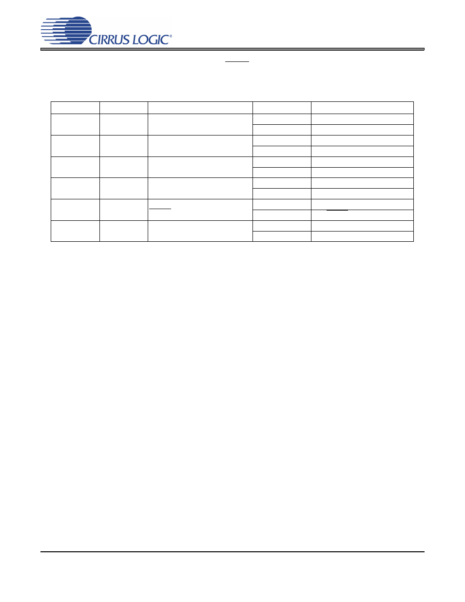
Switch S7 controls the remaining options for the CS8422 in hardware mode, see
for switch config-
urations. The NV/RERR (CS8422 pin 9) and V/AUDIO (CS8422 pin 10) signals are provided at header J26
pins 5 and 2, respectively, and their states are indicated by LEDs D2 and D3. The TX/U (CS8422 pin 18)
signal is provided at pin 1 of J31. If the transmitter pass-through option is selected for this signal, the data
can be sent to the optical and coaxial output S/PDIF connectors by shunting the bottom two pins of J31.
Note:
Position 6 also selects either the CS8422’s RMCK or MCLK_OUT signal to send to the SAO1 head-
er J24 and the CS8406’s OMCK pin.
POSITION
LABEL
PURPOSE
SETTING
FUNCTION SELECTED
1
RX_SELECT
Selects Active Receiver Input
Pins
0
RXP0/RXN0 Selected
1
RXP1/RXN1 Selected
2
TX_SELECT
Selects Receiver Input to be Out-
put to Transmitter Pass-through
0
RXP0/RXN0 Selected
1
RXP1/RXN1 Selected
3
TX_U/OUT
SEL
Selects Transmitter Pass-through
or U Data Output on Pin 18
0
Transmitter Pass-through Output
1
Incoming U Data Output
4
NV/RERR
SEL
Selects NV or RERR Output on
Pin 9
0
NVERR Output
1
RERR Output
5
V/AUDIO SEL
Selects Validity Data Output or
AUDIO Indicator Output on Pin 10
0
Validity Data Output
1
AUDIO Indicator Output
6
SRC MCK
SEL
Selects MCLK Source for Serial
Output Port 1
0
XTI - XTO Selected
1
RMCK Selected
Table 5. S7 Settings