Hardware setup, Captureplus ii – Cirrus Logic CapturePlus II User Manual
Page 5
CapturePlus II
DS789UM2
5
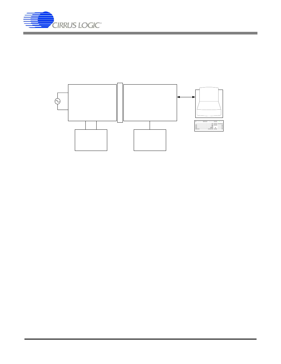
3. HARDWARE SETUP
The following section describes the connections between the Cirrus Logic evaluation board and the Cap-
turePlus II system. It then describes the connections between the CapturePlus II system and the PC.
1.
Plug the ADC evaluation board into the connectors on the top of the CDBXC2S50 board.
2.
Connect the USB cable between the CapturePlus II USB connector and the PC USB port.
3.
With the CapturePlus II system power switch in the OFF position, plug the brick power supply into the
CapturePlus II system. Plug the power supply into a 100-240 VAC, 50/60 Hz, 1.0 A outlet.
4.
Connect the
required power supplies to the appropriate connectors on the
evaluation board.
5.
Slide the CapturePlus II system power switch to the ON position. Press and release the Reset (/POR)
switch, S3.
6.
Turn on the power supplies connected to the evaluation board.
7.
Start the CapturePlus II software.
ADC &
Associated Analog Circuitry
External Power
Supplies
(Not Included)
El
ect
rical Isol
at
io
n
CapturePlus II
Data Capture Hardware
Cirrus Logic
Evaluation Board
IBM-compatible PC
Running CapturePlus II
Software
USB Port
Serial Port
Digital Inputs
Digital Outputs
Analog
Signal
Source
Included Power
Supply