6 bypass control (address 06h), P 22 – Cirrus Logic CDB42448 User Manual
Page 22
CDB42448
22
DS648DB2
5.5.5
LEFT-JUSTIFIED OR I
²
S INTERFACE FORMAT (I
²
S/LJ)
Default = 0
0 - Left-Justified
1 - I
²
S
Function:
Selects either I
²
S or Left Justified interface format for the CS8416. Pin 6 (RST bit) is held low for 300
µs whenever this bit changes.
5.5.6
RMCK MASTERS MCLK BUS (RMCK_MASTER)
Default = 0
0 - Enabled
1 - Disabled
Function:
Enables/disables the external MCLK output buffer on the MCLK bus (see Figure 6 on page 13).
5.6
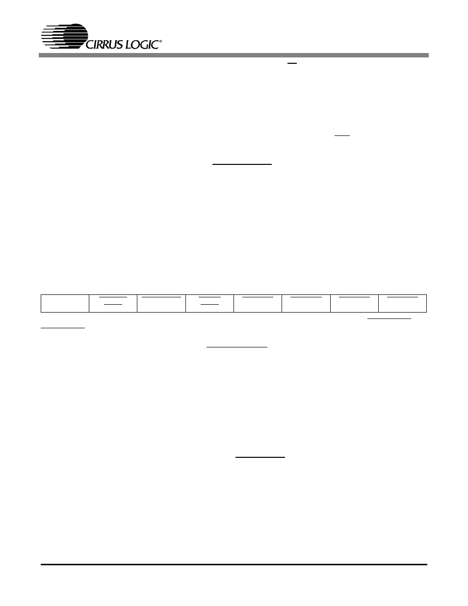
BYPASS CONTROL (ADDRESS 06H)
NOTE: To avoid contention with the FPGA, set the clock direction for the FPGA appropriately: FPGA->DAC and
FPGA->ADC in register 03h and 07h must be set to ‘1’b.
5.6.1
DSP DATA ROUTE TO DAC (DSPDATA->DAC)
Default = 1
0 - Enable
1 - Disable
Function:
This bit toggles a control line for the data buffer external to the FPGA to route the DSP Data directly
to the DAC (see Figure 7 on page 14). The inverted signal controls active low buffers internal to the
FPGA that routes the FPGA data to the DAC. Refer to Figure 4 on page 11.
5.6.2
ADC SDOUT DATA ROUTE TO DSP (SDOUT->DSP)
Default = 1
0 - Enable
1 - Disable
Function:
This bit toggles a control line for the external data buffer to route the ADC Data directly to the DSP
(see Figure 7 on page 14). The inverted signal controls active low buffers external to the FPGA that
7
6
5
4
3
2
1
0
Reserved
DSPDATA
->DAC
SDOUT->DSP
CS5341
->AUX
DAC->DSP
ADC->DSP
DSP->DAC
DSP->ADC