Figure 13.differential input filter, Cs4207, Figure 13. differential input filter – Cirrus Logic CS4207 User Manual
Page 141
DS880F4
141
CS4207
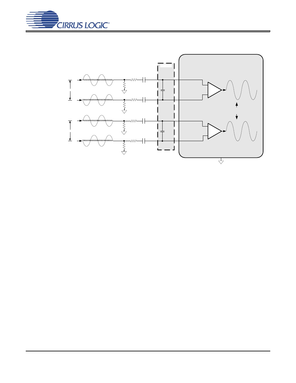
For the best ADC performance, fully differential inputs can be connected to the Mic In 1/Line In 2 input pair
only. This topology provides the best common-mode noise rejection and also increases the dynamic range
due to the larger full-scale input voltage. See
for the recommended differential input filter.
For all of the input topologies, either input pair can be used with a microphone input by connecting the
MICBIAS pin to the signals as shown in
. If electrolytic capacitors are used for AC coupling the mi-
crophone inputs, the positive terminal of the capacitor must be connected to the greater bias voltage. The
analog input pins are internally biased at 0.5*VA and the voltage level of the MICBIAS pin can be configured
by setting the VREFE bits in the
Mic In 1/Line In 2 Pin Widget Control
of the Mic In 1/Line In 2 Pin Widget
(Node ID = 0Dh).
NPO/C0G dielectric capacitors.
Note:
1. These capacitors serve as a charge reservoir for the internal switched capacitor ADC
modulators and should be placed as close as possible to the inputs.
Note 1
*
Low ESR, X 7R/X5 R dielectric capacitors.
**
MICIN_L+
3600 pF
100 k
100
*
1 µF
**
MICIN_L-
CS4207
100 k
100
1 µF
**
MICIN_R+
3600 pF
100 k
100
*
1 µF
**
MICIN_R-
100 k
100
1 µF
**
AGND
+
-
PGA
+
-
PGA
common mode rejection at input of PGA
reduces external system noise
//
Left Analog Input +
(differential traces )
//
Left Analog Input -
//
Right Analog Input +
(differential traces )
//
Right Analog Input -
Figure 13. Differential Input Filter