Typical connection diagrams, Cs4207 – Cirrus Logic CS4207 User Manual
Page 11
DS880F4
11
CS4207
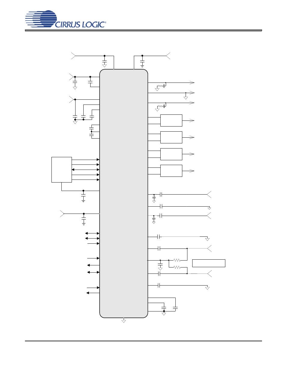
2. TYPICAL CONNECTION DIAGRAMS
1 µF
VREF+
0.1 µF
HP_GND(Thermal Pad)
VL_HD
0.1 µF
+1.5 V to +3.3 V
RESET#
SDI
BITCLK
SYNC
VA
* Capacitors must be C0G or equivalent
MICIN_L+
Differential Mic Left
SDO
CS4207
MICBIAS
HPOUT_L
HPOUT_R
R
L
The value of R
L
is dictated by
the microphone cartridge.
HD Audio
Bus
Left Headphone
FLYP
VHP_FILT+
2.2 µF
Microphone Bias
1 µF
0.47 µF
10 µF
**
**
** Use low ESR
ceramic capacitors.
LINEOUT_L1+
+Left Line Output 1
LINEOUT_L1-
Right Headphone
LINEOUT_R1+
+Right Line Output 1
LINEOUT_R1-
0.1 µF
33
1 µF
MICIN_L-
1 µF
R
L
Differential Mic Right
1 µF
MICIN_R+
MICIN_R-
LINEOUT_L2+
+Left Line Output 2
LINEOUT_L2-
LINEOUT_R2+
+Right Line Output 2
LINEOUT_R2-
GPIO2
GPIO2
GPIO3
GPIO3
SPDIF_IN
SPDIF_OUT1
S/PDIF TX 1
S/PDIF RX
SENSE_A
SENSE_A
DMIC_SDA1
D-Mic In 1
HPREF
0.1 µF
33
Headphone Ground
+5.0 V
Differential to
Single-Ended
Output Filter
Differential to
Single-Ended
Output Filter
Differential to
Single-Ended
Output Filter
Differential to
Single-Ended
Output Filter
VA_HP
2.2 µF
**
FLYN
VHP_FILT-
+1.8 V
0.1 µF
VD
+5.0 V
AGND
10 µF
0.1 µF
**
VL_IF
0.1 µF
+3.3 V
FLYC
VCOM
10 µF
‡ Input and Output
filters are optional.
‡
‡
‡
‡
DMIC_SDA2/
SPDIF_OUT2
D-Mic In 2 / S/PDIF TX 2
DMIC_SCL
D-Mic Clk
LINEIN_L+
LINEIN_C-
LINEIN_R+
Left Analog Input
1 µF
1800 pF
*
1 µF
Right Analog Input
1 µF
1800 pF
*
10 µF
VBIAS
+
VA_REF
0.1 µF
+5.0 V
Figure 1. Typical Connection Diagram - Desktop System
*** See
***