I. calculate r, J. calculate flyback zero-current detection, An368 – Cirrus Logic AN368 User Manual
Page 56
AN368
56
AN368REV2
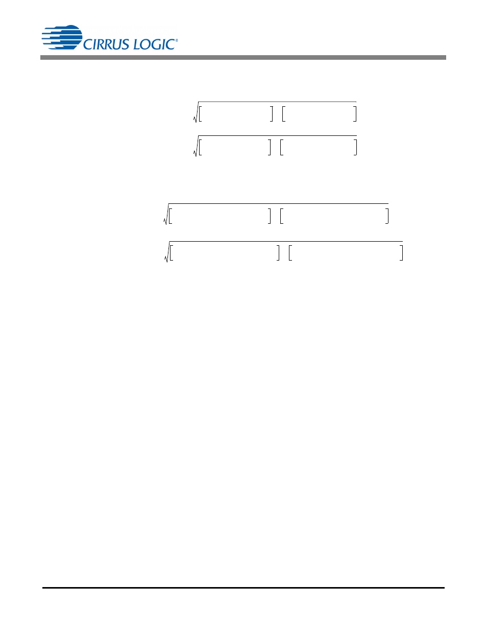
h. Determine the RMS Current in the Winding
The RMS current in the primary winding, I
PRI(RMS)
, is calculated using Equation 29:
The RMS current in the secondary winding, I
SEC(RMS)
, is calculated using Equation 30:
Calculate sense resistor R
Sense
(R21) for flyback using Equation 31:
where,
f
scale
= Scaling factor
R21 = R
Sense
in
Calculate the power P
Sense
dissipated by the sense resistor R
Sense
(R21) using Equation 32:
j. Calculate Flyback Zero-current Detection
Bit VALLEYSW in register Config2 at Address 34 is set to ‘1’, enabling quasi-resonant switching (valley
switching) on the second stage. Bit POL_ZCD in register Config4 at Address 36 is set to ‘0’ configuring the
comparator output to active-low. The transformer TX1 auxiliary winding turns ratio
is calculated using Equation
I
PRI RMS
I
PK1 FB
2
D
MODE1
3
--------------------
I
PK2 FB
2
D
MODE2
3
--------------------
+
=
[Eq. 108]
299mA
2
0.37
3
-----------
237mA
2
0.225
3
---------------
+
=
123.5mA
=
I
SEC RMS
N
2
I
PK1 FB
2
1 D
MODE1
–
3
-----------------------------
N
2
I
PK2 FB
2
1 D
MODE2
–
3
-----------------------------
+
=
[Eq. 109]
5.57
2
299mA
2
1 0.37
–
3
---------------------
5.57
2
237mA
2
1 0.225
–
3
------------------------
+
=
1.016A
=
R
Sense
1.4V
f
scale
I
PK1 FB
-------------------------------------
1.4V
1.1 0.299A
--------------------------------
4.26
=
=
=
[Eq. 110]
P
Sense
I
PRI RMS
2
R
Sense
123.5
mA
2
4.26
65mW
=
=
=
[Eq. 111]
[Eq. 112]
N
P
N
FBAUX
-------------------
2 N V
OVP
R23
1.25V
R22 R23
+
------------------------------------------------------
=
2 5.57 15V 1.1k
1.25V
14k
1.1k
+
---------------------------------------------------------------
=
9.7
=