An368, And white gain (gain, Figure 17. color control system – Cirrus Logic AN368 User Manual
Page 36: Gain, Q3 = d, Q2 d, Q1 d, Ratio i, Color i, White ------------------------ gain
AN368
36
AN368REV2
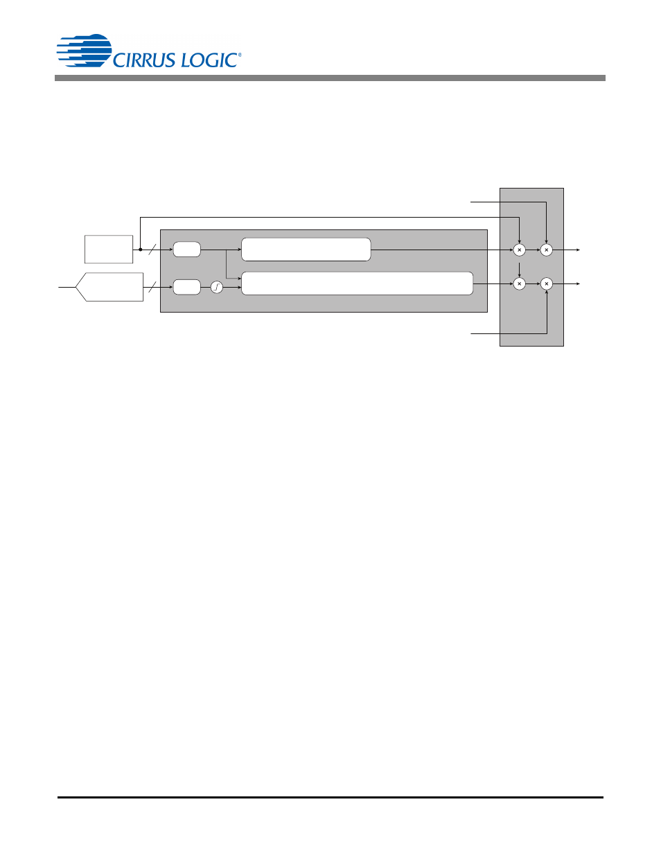
One of the LED strings is composed of red or amber LEDs, and the other string is composed of cool-white or
blue-white LEDs. While the lumen output of white LEDs does not vary significantly across temperature, the
lumen output of red LEDs can vary as much as 40% across temperature. To achieve a stable light output, the
current in the red LED string needs to be compensated with respect to temperature. This is accomplished by
the color control block (see Figure 17). The color control system controls the color temperature of the light by
varying the gain of each channel based on the current dim level. It can also vary the gain of any one channel
based on the temperature sensed by an external NTC thermistor to compensate the for temperature drifts.
The required gain value for a particular combination of dim and temperature is obtained using polynomial
curves, the coefficients for which are programmed into the CS1630/31 OTP memory. A different polynomial is
used for each channel. One of these is a polynomial in two variables—dim and temperature—while the other
is a polynomial in dim only. If D and T are assumed to be the normalized dim and temperature values,
respectively, between 0 and 1.0, then GAIN
DTR
refers to the dim-regulated gain and temperature-regulated
gain, and GAIN
DR
refers to the dim-regulated gain.
The constraints for choosing polynomials to model current behavior are:
• The polynomial coefficients (P30, P20…P00, Q3…Q0) are limited to the range [-8,8].
• The output CCS gain value is limited to the range [0,4].
The color control system provides a mechanism to control the correlated color temperature (CCT) by
controlling the current ratio between the two strings.
The CCT is a function of the current ratios, and the brightness is a function of the weighted sum of the currents
in both channels.
The color control block also implements the color temperature calibration feature by providing the ability to
independently scale the computed gain values ±15% in each channel based on the 6-bit cal-codes
programmed in the OTP memory.
Color gain (GAIN
DTR
) and white gain (GAIN
DR
) can be directed to either output channel using the LED
Arrangement Order (LED_ARG) in register Config3 at Address 35.
dim
NTC
(From Boost)
12
8
ч 4096
ч 256
D
T
Normalize
Normalize
Saturation
Logic
GAIN
DR
= Q3
 D
3
+ Q2
 D
2
+ Q1
 D + Q0
GAIN
DTR
= P30
 T
3
+ P20
 T
2
+ P10
 T + P03  D
3
+ P02
 D
2
+ P01
 D +
P21
 T
2
 D + P12  T  D
2
+ P11
 T  D + P00
I
ref
White
I
ref
Color
I
White
I
Color
dim
dim
Temperature
(ADC Fast Filter)
Figure 17. Color Control System
GAINDTR P30 T
3
P20 T
2
P10
+
+
T
P03 D
3
P02
+
+
D
2
P01 D
P21 T
2
D
+
+
=
P12 T D
2
P11 T D
P00
+
+
+
GAIN
DR
Q3
=
D
3
Q2 D
2
Q1 D
Q0
+
+
+
[Eq. 60]
Ratio
I
Color
I
White
-------------
I
ref
Color
I
ref
White
------------------------
GAIN
DTR
GAIN
DR
-------------------------
=
=
[Eq. 61]
GAIN
CH1
Cal-Factor
CH1
GAIN
DTR
=
GAIN
CH2
Cal-Factor
CH2
GAIN
DTR
=
[Eq. 62]