An368 – Cirrus Logic AN368 User Manual
Page 14
AN368
14
AN368REV2
For optimum efficiency, the increase in transformer losses (created by an uneven duty cycle) must balance the
reduction of the losses caused by discharging the leakage inductance (obtained by increasing the overshoot
voltage). Equation 3 is used to balance all voltages contributing to the FET voltage drain and source.
where,
V
Overshoot
= V
Zener
- V
Reflected
c. Determine the Flyback Transformer Turns Ratio
Select a turns ratio based on the channel output voltage, V
CH1
, V
CH2
, and V
Reflected
where,
V
CH1(max)
= Maximum channel 1 LED forward voltage V
CH1
at full current plus the rectifying diode voltage V
F
.
V
CH2(max)
= Maximum channel 2 LED forward voltage V
CH2
at full current plus the rectifying diode voltage V
F
.
d. Select the Full Brightness Switching Frequency
The CS1630 has two switching events with frequencies F
sw1
and F
sw2
that make up a complete switching
frequency F
sw
. Common criteria for determining the desired switching frequency include:
1. Maximum channel-switching frequencies F
sw1(max)
and F
sw2(max)
are less than 200kHz.
2. Maximum flyback stage switching frequency F
sw(max)
is less than 100kHz.
3. For EMI considerations, the higher switching frequency between the two channels should be less than
75kHz.
4. Switching frequency F
sw
should be in audible range only at low power.
5. Switching frequencies F
sw1
and F
sw2
are selected such that the size of the flyback transformer meets
the converter system form factor requirements.
The maximum switching frequency F
sw(max)
for the second stage is configured using the TTFREQ register at
Address 46. Bits TTFREQ[7:0] set the minimum allowable target period for the second-stage time TT:
[Eq. 3]
V
Breakdown
V
BST max
V
Zener
V
M
in
arg
+
+
=
N
V
Reflected
V
CH1 max
V
CH2 max
+
--------------------------------------------------------------
=
[Eq. 4]
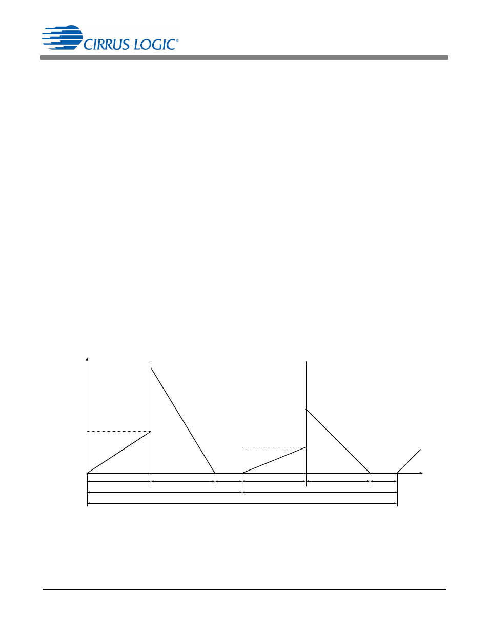
i(t)
T1
CH1
T2
CH1
TT
CH1
No Current
T3
CH1
Secondary
Current
t
T1
CH2
T2
CH2
No Current
T3
CH2
Secondary
Current
TT
TT
CH2
Peak Primary Current 2, I
PK2(FB)
Primary
Current
Peak Primary Current 1, I
PK1(FB)
Primary
Current
Figure 4. Timing Diagram for Switching Frequencies
1
F
sw max
---------------------
TTFREQ[7:0] 4
50ns
=
[Eq. 5]